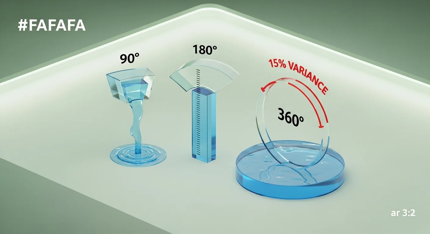
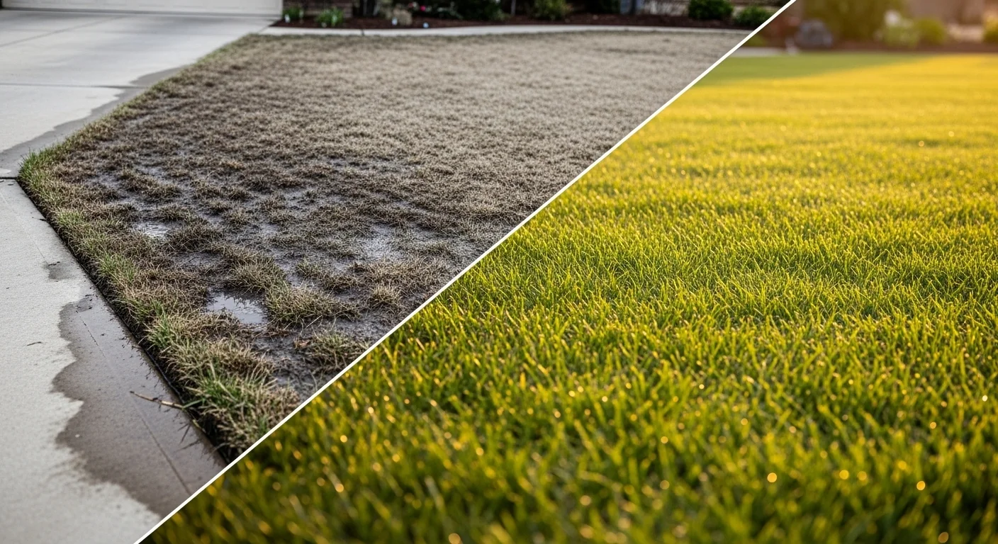
Sprinkler systems fail quietly. Corners go soggy, centers turn brown, and the standard diagnosis is “not enough water” when the real problem is geometric. A 90-degree corner head running the same nozzle as a 360-degree center head delivers precipitation at a rate up to four times higher per square foot, because it concentrates the same flow over a fraction of the coverage area. That imbalance is the Swamp and Desert Effect, and it is entirely predictable from a single formula.
This matched precipitation rate calculator computes the exact precipitation rate in inches per hour for your head type, arc, spacing, and nozzle flow rate. It also runs the same formula across 90-degree, 180-degree, and 360-degree arcs simultaneously using your inputs, so you can see the full imbalance before you touch a nozzle. What it does not do: account for wind drift, pressure variation between heads, or soil slope. Once you have your matched precipitation rate, a companion tool like the sprinkler run time calculator can translate that rate into zone-by-zone run times.
After running this calculator, you will know whether your current nozzle configuration creates a precipitation imbalance exceeding the 15 percent variance threshold, and whether you need arc-specific MPR nozzles to correct it.
Use the Tool
Matched Precipitation Rate Calculator
Eliminate swamp & desert zones — balance irrigation across all head types
Enter your values and click Calculate.
| Arc | Spacing (ft) | Area (ft²) | MPR (in/hr) | Balance |
|---|---|---|---|---|
| Run calculation to populate | ||||
How This Calculator Works — Formula & Assumptions ▼
Step 1 — Calculate the coverage area for your arc:
This gives the actual ground area (in square feet) that one head covers at a given arc and radius (spacing).
Step 2 — Convert GPM to in/hr over that area:
The constant 96.3 converts gallons-per-minute into inches-per-hour over the coverage area. This is the industry-standard Matched Precipitation Rate (MPR) formula.
Step 3 — Compare arc configurations (Swamp & Desert check):
If variance across arcs exceeds 15%, a Swamp & Desert warning is triggered. A 90° corner head with the same nozzle as a 360° center head delivers 4× the precipitation rate — creating soggy corners and drought-stressed centers.
Assumptions & Limits:
- Assumes head-to-head spacing (radius = spacing distance)
- Assumes uniform soil infiltration rate and flat terrain
- Assumes no wind drift or pressure variation between heads
- GPM should be measured at operating pressure (typically 30–45 PSI for rotors, 30 PSI for sprays)
- Valid for spacings 1–60 ft and flow rates 0.1–20 GPM
- Does not account for distribution uniformity (DU) — use catch cups for DU testing
- Arc degree comparison uses 90°, 180°, and 360° as the standard reference trio
- The 15% variance threshold is based on ASABE/EPA WaterSense irrigation guidelines
Before entering values, have your nozzle specification sheet or manufacturer data on hand. You need the rated GPM at your operating pressure, not the maximum listed on the packaging. Head spacing should be the actual installed distance between heads (measured center-to-center), not the manufacturer’s throw radius. Arc degree is the pattern angle of the head as installed, which may differ from the nozzle’s maximum arc if it has been adjusted. If you are unsure what your system is actually delivering at each head, an irrigation catch can test will give you field-measured precipitation data to cross-reference against this calculator’s output.
Quick Start (60 Seconds)

- Sprinkler Head Type: Select Rotor for gear-driven heads that rotate slowly across the arc, or Pop-up Spray for fixed-pattern heads. Mixing types on the same zone is a common design error.
- Arc Degrees: Choose the arc as installed, not the nozzle maximum. A 90-degree corner head configured to spray 110 degrees is not a 90-degree arc for this calculation.
- Head Spacing (ft): Enter the distance between adjacent heads, center-to-center, in feet. Do not use the manufacturer’s listed radius if your installation differs. Valid range is 1 to 60 feet.
- Nozzle Flow Rate (GPM): Use the GPM figure from the nozzle’s performance chart at your actual operating pressure, typically 30 PSI for spray heads and 35 to 45 PSI for rotors. Do not read the flow from the box label without checking pressure.
- Check the arc comparison cards: The results panel shows computed MPR for 90, 180, and 360 degrees using your GPM and spacing. If the variance between cards is large, the warning will tell you exactly how far out of balance the system is.
- Check the gauge bar: Balanced zone is below 1.2 in/hr. The watch zone runs from 1.2 to 1.8. Above 1.8 in/hr, most clay and loam soils cannot absorb water fast enough to prevent runoff.
- Use Reset between scenarios: If you are testing multiple nozzle sizes or spacings, click Reset to clear all fields before re-entering. Results do not update live once calculated.
Inputs and Outputs (What Each Field Means)
| Field | Unit | What it means | Common mistake | Safe entry guidance |
|---|---|---|---|---|
| Sprinkler Head Type | Category | Identifies the head’s water delivery pattern: rotors sweep slowly across the arc while spray heads deliver a fixed fan pattern instantly | Mixing head types on the same zone and treating them as equivalent | Run rotors and spray heads on separate zones; they have fundamentally different precipitation rate profiles |
| Arc Degrees | Degrees (°) | The angular sweep of the spray pattern. Corner heads are typically 90°, edge heads 180°, center heads 360° | Selecting 90° for a head that has been field-adjusted to 120° or 135° | Measure the arc with a protractor or count degrees using the adjustment marks on the head body before entering |
| Head Spacing | Feet (ft) | The distance between heads, center to center. The formula uses this as the coverage radius in the area calculation | Using the manufacturer’s listed throw radius instead of actual installed spacing | Measure installed spacing with a tape measure. Accepted range: 1 to 60 feet |
| Nozzle Flow Rate | GPM | The volumetric flow rate through the nozzle at operating pressure. This is the numerator in the MPR formula | Using maximum rated GPM rather than GPM at actual system pressure | Look up GPM from the nozzle’s pressure-flow table at your operating pressure. Valid range: 0.1 to 20 GPM |
| Primary MPR Result | in/hr | The matched precipitation rate for your exact arc, spacing, and GPM combination | Treating this number as a soil infiltration rate; it is a delivery rate, not absorption capacity | Compare against your soil’s infiltration rate; use cycle-and-soak if MPR exceeds infiltration capacity |
| Arc Comparison Cards (90 / 180 / 360) | in/hr each | The MPR that would result if your GPM and spacing were applied at each of the three standard arc configurations | Ignoring these comparison values and focusing only on the primary result | If your system has multiple arc heads on the same zone, all three cards are relevant to your actual coverage imbalance |
Soil intake capacity is the limiting factor that the calculator does not compute directly. The soil infiltration rate calculator can help you determine whether your MPR result exceeds what your soil can accept before runoff begins.
Worked Examples (Real Numbers)
Scenario 1: Classic Swamp and Desert Setup (Rotors, Mixed Arcs, Same Nozzle)
A homeowner installs eight rotors: four 90-degree corner heads and four 360-degree center heads, all using 3.0 GPM nozzles at 15-foot spacing.
- Arc (corner): 90°
- Arc (center): 360°
- Spacing: 15 ft
- GPM: 3.0
Area at 90°: 3.14159 × 225 × (90/360) = 176.7 ft²
Area at 360°: 3.14159 × 225 × (360/360) = 706.9 ft²
PR at 90°: 96.3 × 3.0 / 176.7 = 1.63 in/hr
PR at 360°: 96.3 × 3.0 / 706.9 = 0.41 in/hr
Result: The 90-degree corner head delivers 1.63 in/hr while the center head delivers 0.41 in/hr. The corner receives nearly four times the precipitation of the center at identical nozzle output.
This is a textbook Swamp and Desert configuration. The corners will exhibit waterlogging and possible fungal disease, while the center zone shows heat stress and browning. Correcting this requires installing 0.75 GPM nozzles in the 90-degree corner heads, or switching to an arc-matched MPR nozzle series.
Scenario 2: Balanced Edge Spray Head (180°, Short Spacing)
- Head type: Pop-up Spray
- Arc: 180°
- Spacing: 10 ft
- GPM: 1.5
Area: 3.14159 × 100 × (180/360) = 157.1 ft²
PR: 96.3 × 1.5 / 157.1 = 0.92 in/hr
Result: 0.92 in/hr, comfortably in the balanced zone.
This configuration is suitable for clay or sandy loam soils. The precipitation rate stays below the 1.2 in/hr threshold, leaving headroom for minor pressure variation without risking runoff.
Scenario 3: Three-Quarter Rotor on a Large Turf Zone (270°, Wide Spacing)
- Head type: Rotor
- Arc: 270°
- Spacing: 20 ft
- GPM: 4.0
Area: 3.14159 × 400 × (270/360) = 942.5 ft²
PR: 96.3 × 4.0 / 942.5 = 0.41 in/hr
Result: 0.41 in/hr, well within the balanced zone.
Wide spacing and a high arc degree combine to distribute 4.0 GPM over a large area. This configuration is appropriate for established turf with no runoff concerns, though the low precipitation rate means longer run times are needed to reach target soil moisture depth.
Reference Table (Fast Lookup)
The following table uses a fixed flow rate of 3.0 GPM and varies arc and spacing. The MPR column is derived directly from the formula PR = 96.3 × GPM / (π × spacing² × arc/360). Use this for quick nozzle-matching decisions without running the calculator for each scenario.
| Arc | Spacing (ft) | Coverage Area (ft²) | MPR at 3.0 GPM (in/hr) | MPR at 1.5 GPM (in/hr) | Balance Zone |
|---|---|---|---|---|---|
| 90° | 10 | 78.5 | 3.68 | 1.84 | Swamp Risk |
| 90° | 12 | 113.1 | 2.56 | 1.28 | Swamp Risk / Watch |
| 90° | 15 | 176.7 | 1.63 | 0.82 | Watch / Balanced |
| 180° | 10 | 157.1 | 1.84 | 0.92 | Swamp Risk / Balanced |
| 180° | 12 | 226.2 | 1.28 | 0.64 | Watch / Balanced |
| 180° | 15 | 353.4 | 0.82 | 0.41 | Balanced |
| 270° | 12 | 339.3 | 0.85 | 0.43 | Balanced |
| 270° | 15 | 530.1 | 0.54 | 0.27 | Balanced |
| 360° | 15 | 706.9 | 0.41 | 0.20 | Balanced |
| 360° | 20 | 1256.6 | 0.23 | 0.11 | Balanced |
Notice how the 90-degree corner at 10-foot spacing with 3.0 GPM produces 3.68 in/hr, while the 360-degree center at 15-foot spacing with the same nozzle produces 0.41 in/hr. That is the geometry of the Swamp and Desert Effect in numerical form.
How the Calculation Works (Formula and Assumptions)

Show the calculation steps
Step 1: Compute the coverage area.
The formula treats the head spacing as the effective spray radius and computes the area of a circular sector:
Area (ft²) = π × Spacing² × (Arc ÷ 360)
At 90 degrees and 15-foot spacing: Area = 3.14159 × 225 × 0.25 = 176.7 ft². At 360 degrees with the same spacing: Area = 3.14159 × 225 × 1.0 = 706.9 ft². The quarter-circle covers one-quarter the area of the full circle, which is why corner heads concentrate water so severely.
Step 2: Convert GPM to precipitation rate.
PR (in/hr) = 96.3 × GPM ÷ Area (ft²)
The constant 96.3 is a unit conversion factor that translates gallons per minute over square feet into inches per hour. It is derived from: 1 gallon = 0.1337 cubic feet; 1 foot = 12 inches; 60 minutes per hour. The result is: (1 / 0.1337) × (1 / 12) × 60 ≈ 96.3.
Step 3: Compute the arc variance check.
Variance (%) = (Max PR − Min PR) ÷ Min PR × 100
The calculator computes this across the standard trio (90°, 180°, 360°) using your GPM and spacing. If the result exceeds 15, the Swamp and Desert warning fires. Rounding: MPR values are shown to two decimal places. Area is rounded to one decimal place in the reference table but carries full precision in the variance calculation.
Assumptions and Limits
- The formula assumes head-to-head spacing: that is, the spacing distance equals the spray radius. If heads are under-spaced or over-spaced relative to their throw radius, actual precipitation distribution will differ from the computed value.
- Uniform operating pressure is assumed across all heads on the zone. Pressure variation caused by elevation change, pipe friction, or valve wear will alter actual GPM and therefore the true precipitation rate. Pipe friction loss in lateral lines can be estimated with the PVC friction loss calculator to check whether pressure variation is significant.
- No wind drift correction is applied. Even moderate wind substantially reduces precipitation uniformity in spray heads; rotors are less affected due to their lower trajectory and larger droplet size.
- The formula does not account for distribution uniformity (DU). A DU value below 0.65 means significant dry spots regardless of MPR balance. Field catch cup testing is the only way to measure DU directly.
- Soil slope is not considered. On slopes exceeding 8 to 10 percent grade, even balanced MPR configurations may require cycle-and-soak irrigation schedules to prevent runoff before water infiltrates.
- GPM entered should be at actual operating pressure, not maximum rated pressure. Most nozzle data sheets list flow at multiple pressure points. Using the wrong column understates or overstates computed MPR.
- The 15-percent variance threshold referenced in the Swamp and Desert warning is drawn from industry guidance on matched precipitation rate design; it is not a regulatory compliance threshold for all jurisdictions.
- This calculator is valid for spacings between 1 and 60 feet and flow rates between 0.1 and 20 GPM. Values outside these ranges may produce physically unrealistic results and are rejected by the input validation.
Standards, Safety Checks, and “Secret Sauce” Warnings
Critical Warnings
- The Same Nozzle, Different Arc = Different Zone: Using identical nozzles on corner and center heads is the single most common installation error in residential irrigation. A 90-degree head with the same GPM as a 360-degree head delivers four times the precipitation per square foot. This is not a minor imbalance; it is the geometric difference between a quarter-circle and a full circle. The fix is not adjusting run time. It is matching nozzle GPM to arc so that all heads converge on the same target precipitation rate.
- MPR Above 1.8 in/hr on Clay or Loam Soils: Most established lawns on clay or loam soils have infiltration rates well below 1.5 in/hr. An MPR result above 1.8 in/hr means the system is likely applying water faster than the soil can absorb it during a continuous run, producing puddles, compaction, and wasted water regardless of how many minutes the zone runs. Cycle-and-soak scheduling partially mitigates this, but nozzle downsizing or spacing adjustment is the preferred correction.
- Pressure at the Head Matters More Than Pressure at the Valve: GPM is pressure-dependent. A pressure drop of 10 PSI across a long lateral line can reduce actual GPM by a measurable amount, shifting your calculated MPR lower than what the system actually delivers at the valve end of the zone and higher at the far end. System pressure should be checked at head level, not just at the backflow preventer.
- Rotors and Spray Heads Must Not Share a Zone: Rotor precipitation rates typically range from 0.2 to 0.7 in/hr, while pop-up sprays commonly run from 1.0 to 2.0 in/hr on the same spacing. Placing them on the same zone makes MPR balancing mathematically impossible regardless of nozzle choice.
Minimum Standards
- Arc-matched MPR nozzle sets (such as the Hunter PGP Ultra MPR series or Rain Bird matched-rate nozzles) are designed so that the 90-degree nozzle delivers one-quarter the GPM of the 360-degree nozzle, producing identical in/hr across all arc configurations at the same spacing. These are the hardware-level solution to the Swamp and Desert Effect.
- The 15-percent variance threshold used in this calculator is consistent with WaterSense program guidance on matched precipitation rate design. Systems exceeding this threshold on any zone should be flagged for nozzle replacement before adjusting controller run times.
- Head-to-head coverage (where each head’s throw radius reaches the adjacent head) is the design standard that makes the spacing assumption in this formula valid. Systems that deviate significantly from head-to-head coverage will show higher dry-spot frequency than the MPR calculation predicts. Checking the wire sizing and controller capacity is also part of a complete system audit; the irrigation wire size calculator can confirm whether the electrical infrastructure supports the zone load.
Competitor Trap: Most matched precipitation rate articles and online calculators present the MPR formula for a single arc configuration and stop there. They tell you what your current head delivers, but not how that compares to the other heads on the same system. This is the precise gap where homeowners and contractors get burned. Knowing that your 180-degree edge head runs at 0.82 in/hr is not actionable if you do not also know that your 90-degree corner is running at 1.63 in/hr on the same zone. The variance between those two numbers is what creates the problem. Any tool or article that skips the multi-arc comparison is giving you half the diagnostic.
Common Mistakes and Fixes
Mistake: Using Maximum Rated GPM Instead of Pressure-Specific GPM
Nozzle packaging lists a maximum GPM that corresponds to the highest rated pressure. Most residential systems operate at 30 to 40 PSI at the head, which is below the maximum rating. Using the maximum GPM in the calculator overstates precipitation rate, making a watch-zone configuration appear to be in the safe zone. Always locate the pressure-flow chart for your specific nozzle model and enter the GPM value at your actual operating pressure. If you are not certain of your system’s flow capacity, the hose flow rate calculator can help estimate flow from your supply connection.
Mistake: Measuring the Spray Radius Instead of Head Spacing
The formula uses head spacing (center-to-center distance) as the radius input. This works correctly when the system is designed to head-to-head coverage, where spacing equals throw radius. When the manufacturer’s listed throw radius is longer than the installed spacing, entering the throw radius inflates the computed coverage area and understates actual MPR. The result is a calculation that looks balanced on screen but underdelivers in dry zones.
Fix: Measure the actual installed distance between adjacent heads on the ground and enter that number.
Mistake: Treating MPR as the Watering Depth Per Run
MPR is a rate (inches per hour), not a depth per run. Multiplying MPR by run time gives you the inches of water applied, which is useful for scheduling but is not what the calculator displays. Confusing the two leads to wildly incorrect run-time estimates. A 0.5 in/hr system running for 30 minutes applies 0.25 inches of water, not 0.5 inches.
Fix: Use the precipitation rate from this calculator as the input to a run time calculator to determine how long to run each zone to hit a target application depth.
Mistake: Assuming a Single-Zone Fix Corrects the Entire System
If the corner-vs-center variance is severe on Zone 1, the same geometric problem almost certainly exists on every other zone in the system that uses the same nozzle type. Replacing corner nozzles on Zone 1 only and leaving Zone 2 through Zone 6 unchanged is a partial fix that will still produce uneven coverage system-wide.
Fix: Run the calculator for each zone individually and audit nozzle selection across the entire system before purchasing replacement hardware.
Mistake: Confusing Arc Adjustment With Nozzle Replacement
Reducing the arc on a corner head from 120 degrees to 90 degrees does not lower the GPM; it concentrates the same flow into a smaller arc, which increases MPR rather than balancing it. Arc adjustment controls pattern shape and overlap. Nozzle replacement controls GPM. These are separate levers with opposite effects on precipitation rate when arc is changed.
Fix: To reduce MPR on a corner head, select a nozzle with a lower GPM rating. Do not use arc reduction as a substitute for matched nozzle sizing.
Next Steps in Your Workflow
Once you have the MPR values for each zone in your system, the next decision is whether your run times are set correctly to hit your target watering depth. MPR tells you the rate of application; the quantity applied depends on how long the zone runs. For turf, a typical target is 1 to 1.5 inches of water per week depending on turf type, temperature, and evapotranspiration demand. The evapotranspiration calculator can help you determine the actual weekly water demand for your climate so you are applying the right total volume, not just the right rate.
If your MPR result is in the balanced zone but you are still seeing dry patches or waterlogged spots, field verification is the next step. Catch cup tests measure what is actually reaching the turf surface, accounting for overlap patterns, wind effects, and head-to-head distribution that the formula cannot capture. Once you have confirmed that your irrigation coverage is genuinely balanced, you can then evaluate whether the system’s total water delivery matches your soil’s root zone capacity, using tools like the drip irrigation run time calculator if you are considering converting low-efficiency zones to drip for shrub beds or borders.
FAQ
What is matched precipitation rate in irrigation?
Matched precipitation rate (MPR) is a design principle where every sprinkler head on a zone delivers the same amount of water per hour per square foot, regardless of arc angle. It is achieved by proportionally reducing the nozzle flow rate for smaller arcs so that a 90-degree head and a 360-degree head, running identical nozzles by design, produce the same application depth per unit area over the same run time.
Why does a 90-degree corner head apply more water than a center head?
The coverage area of a sprinkler head is proportional to its arc angle. A 90-degree head covers one-quarter of the circular area that a 360-degree head covers at the same spacing. If both heads use the same GPM nozzle, the corner head concentrates all that flow into one-quarter the area, producing four times the precipitation rate. This geometric relationship is why MPR nozzles exist: they scale GPM proportionally to arc.
What is the 15-percent MPR variance threshold?
The 15-percent variance threshold used in this calculator flags when the spread between the highest and lowest precipitation rates across different arc configurations exceeds 15 percent of the lowest rate. This level of imbalance is generally considered the point at which visible symptoms (dry zones and wet zones on the same irrigation circuit) become likely during normal irrigation scheduling. It is consistent with industry-standard matched precipitation rate design guidance.
Can I fix MPR imbalance by adjusting run times?
No. Run time adjustments cannot correct MPR imbalance because all heads on the same zone run for the same duration. If the corner head applies water at four times the rate of the center head, running the zone longer gives the corner four times more water and the center four times more water simultaneously. The imbalance ratio stays the same. The only correct fix is hardware: replace nozzles to equalize precipitation rates across all arcs before adjusting run times.
Do MPR nozzles cost significantly more than standard nozzles?
MPR nozzle racks typically cost modestly more than standard nozzle sets, but the cost is minor compared to the ongoing water waste, turf damage repair, and fungicide treatments that result from chronic over-irrigation in corner zones. Most manufacturers offer MPR or matched-series nozzles as a standard product line, including Hunter’s Pro-Spray MPR nozzles and Rain Bird’s matched-precipitation-rate rotary nozzles, both widely available at irrigation supply houses.
How does head spacing affect matched precipitation rate?
Head spacing directly affects the calculated coverage area in the formula. Wider spacing produces a larger coverage area and therefore a lower precipitation rate at the same GPM. Two heads with identical arc angles but different spacings will produce different MPR values even with the same nozzle. This is why spacing must be measured and entered accurately for the calculator result to be meaningful, and why spacing changes are a valid design lever for adjusting precipitation rate without changing nozzles.
Conclusion
The Swamp and Desert Effect is not a mystery once you run the numbers. The matched precipitation rate formula is straightforward arithmetic, and this calculator applies it simultaneously across arc configurations so you can see the imbalance in hard numbers rather than diagnosing it by dead patches. The single most important thing to take from this page: the arc angle of a head and the GPM of its nozzle cannot be chosen independently if you want even precipitation. They are linked by geometry, and that geometry determines everything that happens to your turf.
The most common mistake is installing a system with uniform nozzles across every head type and then trying to compensate with run-time adjustments that cannot actually fix the underlying delivery imbalance. If your calculation shows a significant variance between corner and center arcs, the correction lives in the nozzle, not the controller. Understanding your soil’s ability to absorb what the system delivers is the next layer of the problem; the field capacity soil moisture calculator can help you set a target that keeps irrigation matched to what the root zone can hold.
Lead Data Architect
Umer Hayiat
Founder & Lead Data Architect at TheYieldGrid. I bridge the gap between complex agronomic data and practical growing, transforming verified agricultural science into accessible, mathematically precise tools and guides for serious growers.
View all tools & guides by Umer Hayiat →