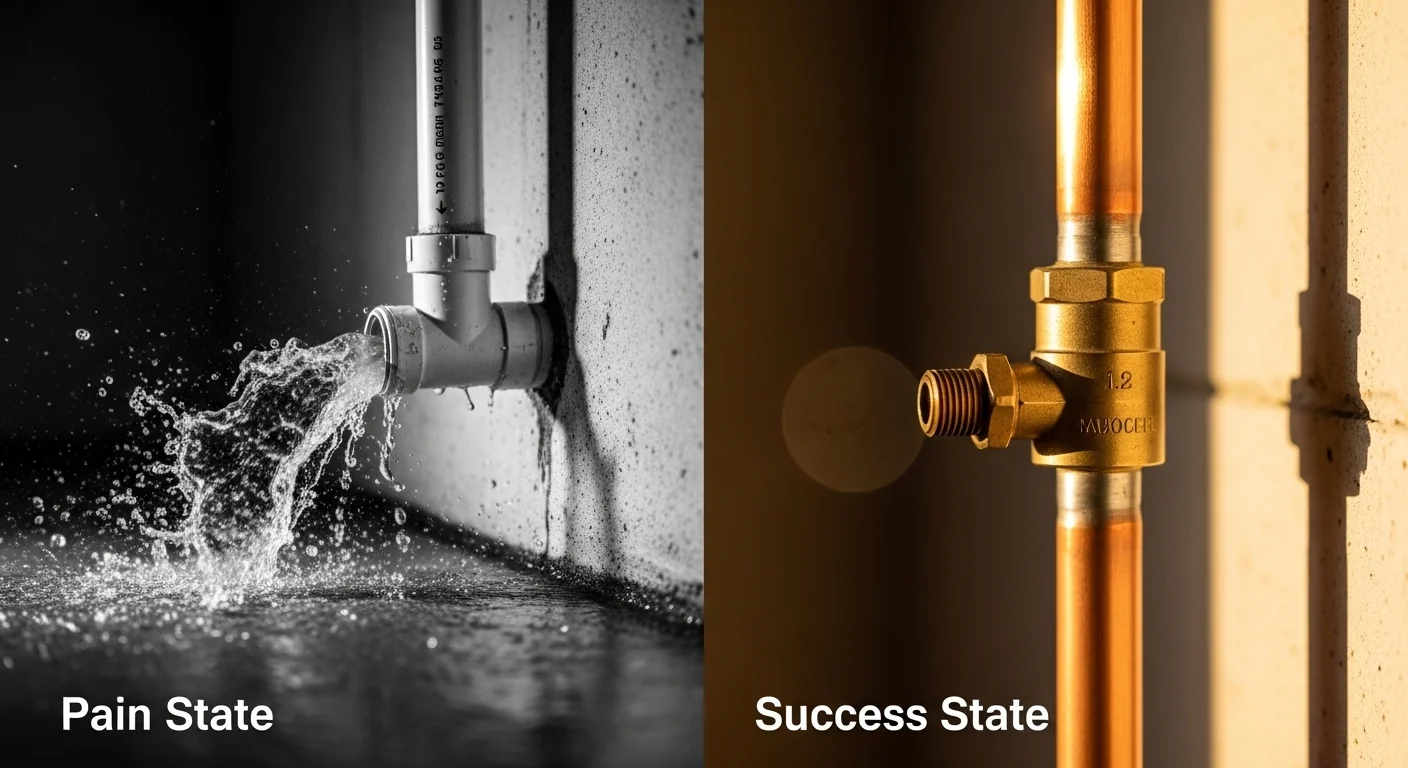
A pipe system running smoothly at 5 ft/s carries real kinetic energy. When a valve snaps shut in 0.1 seconds, that energy does not disappear. It converts instantly into a pressure shockwave traveling at the speed of sound through the pipe material. The Joukowsky equation quantifies that shockwave in PSI and compares it to your pipe’s rated burst pressure. The result is either a manageable transient or a fitting failure waiting to happen.
This water hammer calculator applies the Joukowsky equation to compute surge pressure from four inputs: fluid velocity, valve closure time, pipe length, and pipe material. It identifies whether closure is instantaneous or gradual relative to the critical closure time (Tc), applies the appropriate surge formula, and flags conditions that exceed your pipe’s pressure rating. It does not model column separation, multi-valve systems, or pump-induced transients, which require full hydraulic transient software. When planning pipe sizing and friction losses alongside this analysis, the PVC friction loss calculator covers head loss under steady-state flow conditions.
Once you enter your four inputs and run the calculation, you will know whether your system needs a water hammer arrestor, a slow-close valve, or no action at all, based on arithmetic rather than guesswork.
Use the Tool
Water Hammer Surge Pressure Calculator
Joukowsky Equation — Pipe shockwave & PSI surge analysis
Warnings & Standards
Reference: Surge PSI by Velocity (Your Pipe & Length)
| Velocity (ft/s) | Surge PSI | Condition |
|---|
How This Calculator Works
a is determined by the material:
PVC ~1,200 ft/s, Copper ~3,800–4,000 ft/s, Steel ~4,500 ft/s, HDPE ~700 ft/s.
Stiffer pipe = faster wave = higher surge.
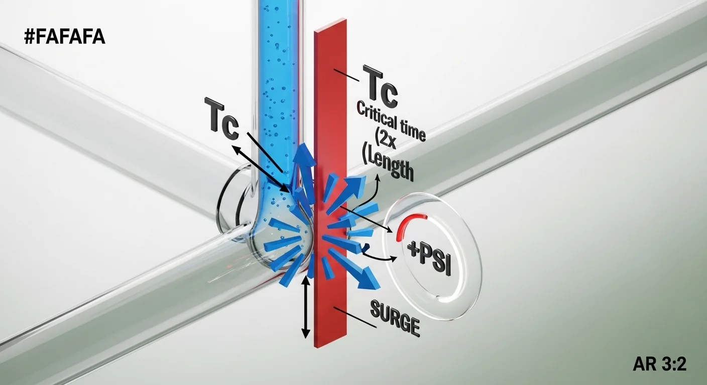
Tc = (2 × Pipe Length) / aThis is the time it takes the shockwave to travel from the valve to the pipe start and back. If the valve closes in less time than
Tc, the closure is instantaneous and the full Joukowsky surge applies.
Surge PSI = (ρ × a × ΔV) / (144 × g)Where: ρ = fluid density (62.4 lb/ft³ for water), a = wave speed (ft/s), ΔV = velocity change (ft/s), g = 32.174 ft/s².
If closure time > Tc, the effective surge is reduced proportionally:
Surge PSI × (Tc / ClosureTime).
Assumptions & Limits
- Fluid assumed to be water at 60°F (ρ ≈ 62.4 lb/ft³; g = 32.174 ft/s²).
- Wave speeds are approximate industry values for standard pipe dimensions; actual values depend on wall thickness, diameter, and pipe support conditions.
- Instantaneous closure Joukowsky formula assumes full velocity drop to zero (valve fully closes).
- Gradual closure reduction (Tc/t_close) is a linear approximation; actual surge shape depends on valve characteristic curve.
- Pipe pressure ratings shown are typical for residential/irrigation sizes (½”–1″) at 73°F. Ratings decrease with higher temperature and larger diameter.
- Does not account for column separation, vapor pressure, or existing static system pressure (static pressure adds to surge).
- For engineered systems (commercial, municipal), consult a licensed mechanical engineer and perform full transient analysis.
- Valid input ranges: Velocity 0.01–50 ft/s, Closure Time 0.001–600 s, Pipe Length 1–10,000 ft.
Before running the calculation, gather three measurements: the flow velocity in the pipe just before the valve closes (from a flow meter, pump curve, or the hose flow rate calculator), the valve closure time in seconds (check the solenoid valve datasheet or time a manual valve with a stopwatch), and the pipe length in feet from the water source to the valve. Select your pipe material from the dropdown. The calculator uses that material selection to assign a wave speed and a typical pressure rating for comparison.
Quick Start (60 Seconds)
- Fluid Velocity (ft/s): Enter the flow velocity inside the pipe immediately before closure, not the velocity at the hose bib or nozzle. Typical residential supply lines run 2 to 8 ft/s. Enter 0.01 as the minimum; the field rejects zero.
- Valve Closure Time (seconds): Solenoid irrigation valves close in 0.05 to 0.2 seconds. Slow-close or motorized ball valves typically take 5 to 30 seconds. Ball valves closed by hand in one quick turn fall in the 0.3 to 1 second range. Do not guess; look up the spec sheet.
- Pipe Length (ft): Measure from the feed point (pump discharge, meter, or manifold) to the valve. If multiple branches exist, use the longest run feeding the valve in question.
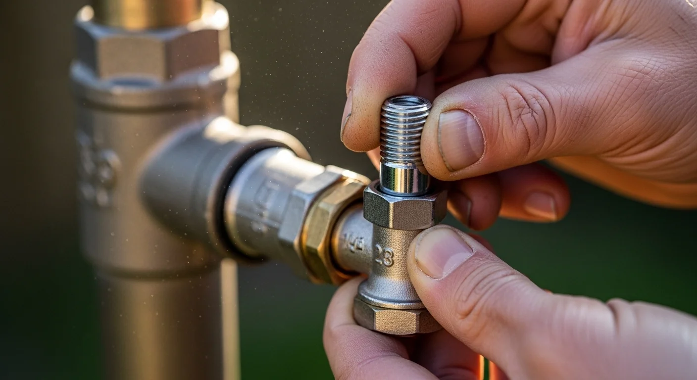
- Pipe Material: Select the material of the pipe carrying flow to the valve. If the run transitions materials (e.g., copper to PVC), select the material closest to the valve, as the wave reflects off changes in impedance.
- Read the Critical Closure Time (Tc): This output tells you the round-trip travel time of the shockwave. If your closure time is shorter than Tc, you are in the danger zone for full Joukowsky surge.
- Check the gauge and badge: Green means within the pipe rating. Orange means approaching the limit. Red with a shatter warning means the calculated surge exceeds the pipe's rated pressure, and failure is mathematically predictable.
- Use the reference table: The table at the bottom of the results shows surge PSI across a range of velocities for your selected material and pipe length, so you can see how sensitive the result is to velocity changes.
Inputs and Outputs (What Each Field Means)
| Field | Unit | What It Represents | Common Mistake | Safe Entry Guidance |
|---|---|---|---|---|
| Fluid Velocity Before Closure | ft/s | The velocity of water moving through the pipe the instant before the valve closes. This is the full kinetic energy available to convert into surge pressure. | Using nozzle or outlet velocity instead of pipe velocity. Nozzle velocity is much higher due to area reduction and will overstate surge. | Use pipe cross-section area and flow rate to compute: V = Q / A. Or pull from a pump curve at the operating point. |
| Valve Closure Time | seconds | The elapsed time from when the valve begins closing to when flow reaches zero. Short closure times create instantaneous surge; longer times partially attenuate it. | Entering 0 or a near-zero value for solenoids. Solenoid valves have a real closure time (typically 0.05 to 0.2 s); they are not instantaneous, but they are almost always faster than Tc. | Check the solenoid or valve datasheet. Hunter and Rain Bird publish close times in their spec sheets. |
| Pipe Length | ft | The distance from the source (pump, meter, or manifold) to the closing valve. Longer pipes produce a longer critical time, which means gradual closure is more achievable. | Measuring only the last segment to the valve rather than the full run from the pressure source. Shockwave travel time depends on the entire pressurized column length. | Walk the pipe run or check blueprints. Add 10 ft for each 90-degree elbow as a conservative allowance. |
| Pipe Material | selection | Determines the acoustic wave speed (a) through the pipe wall and fluid. Stiffer materials transmit shockwaves faster, producing higher surge for the same velocity. | Selecting copper when the run is PVC-to-copper mixed. The wave speed changes at the material transition, and the weaker material governs failure risk. | Select the material carrying flow to the valve. When in doubt, use the softer/lower-rated material to be conservative. |
| Surge Pressure (output) | PSI | The calculated pressure spike above static pressure caused by the velocity change at valve closure. This is added to whatever static pressure already exists in the line. | Treating surge PSI as the only pressure on the pipe. Operating static pressure plus surge is the actual instantaneous pipe wall stress. | Add your static operating pressure (from a gauge or the pipe volume calculator) to the surge PSI before comparing to the pipe rating. |
| Wave Speed / a (output) | ft/s | The acoustic velocity of the pressure wave through the specific pipe material. This is a material property, not a flow velocity. | Confusing wave speed with fluid velocity. They are entirely different quantities; wave speed is 100 to 300 times faster than typical pipe flow. | Read-only output. Verify it matches known values for your material from engineering references. |
| Critical Closure Time / Tc (output) | seconds | The time for a shockwave to travel from the valve to the source and return. Closing the valve in less than Tc creates maximum surge regardless of how fast closure happens within that window. | Assuming a "slower" fast valve avoids the problem. A 0.15-second closure on a 300-foot PVC run with Tc = 0.5 seconds still triggers full Joukowsky surge. | Read-only output. Use it to determine whether a slow-close valve with a close time greater than Tc will meaningfully reduce surge in your system. |
| Pipe Pressure Rating (output) | PSI | A typical rated working pressure for the selected material at standard residential pipe sizes and 73 degrees F. Used as the failure threshold in the safety check. | Assuming the displayed rating matches your specific pipe diameter and temperature. Ratings decrease with larger diameters and elevated temperatures. | Always cross-reference with the actual pipe manufacturer's spec sheet for your exact size and service temperature. |
Worked Examples (Real Numbers)
Example 1: Irrigation Solenoid on a Long PVC Run (Shatter Risk)
- Fluid Velocity: 8 ft/s
- Valve Closure Time: 0.1 seconds (standard irrigation solenoid)
- Pipe Length: 200 ft
- Pipe Material: PVC Schedule 40 (a = 1,200 ft/s, rated 160 PSI)
Critical Time Tc = (2 x 200) / 1,200 = 0.333 seconds. Closure time 0.1 s is less than Tc, so full instantaneous surge applies.
Surge PSI = (62.4 x 1,200 x 8) / (144 x 32.174) = 599,040 / 4,633 = 129 PSI
Result: 129 PSI surge, which is 81% of the 160 PSI pipe rating.
This is classified as high surge. The margin is only 31 PSI before failure. Adding 40 to 60 PSI of static supply pressure to the surge brings the actual instantaneous pipe stress to 169 to 189 PSI, which exceeds the rating. The solution is a water hammer arrestor or a slow-close solenoid with a close time greater than 0.333 seconds.
Example 2: Same System With a Slow-Close Valve Installed
- Fluid Velocity: 8 ft/s
- Valve Closure Time: 10 seconds (Hunter Pro-C compatible slow-close)
- Pipe Length: 200 ft
- Pipe Material: PVC Schedule 40 (a = 1,200 ft/s)
Tc = 0.333 seconds. Closure time 10 s exceeds Tc, so surge is reduced proportionally.
Surge PSI = 129 x (0.333 / 10) = 129 x 0.0333 = 4.3 PSI
Result: 4.3 PSI surge.
The slow-close valve reduces surge by a factor of 30 compared to the standard solenoid. This is a direct, arithmetic demonstration of why valve selection matters more than pipe material in most residential irrigation scenarios.
Example 3: Steel Pump Discharge Line, Near-Critical Closure
- Fluid Velocity: 10 ft/s
- Valve Closure Time: 0.5 seconds (motor-actuated gate valve)
- Pipe Length: 1,000 ft
- Pipe Material: Galvanized Steel (a = 4,500 ft/s, rated 800 PSI)
Tc = (2 x 1,000) / 4,500 = 0.444 seconds. Closure time 0.5 s is greater than Tc, so surge is reduced.
Instantaneous surge = (62.4 x 4,500 x 10) / (144 x 32.174) = 2,808,000 / 4,633 = 606 PSI
Reduced surge = 606 x (0.444 / 0.5) = 606 x 0.889 = 539 PSI
Result: 539 PSI surge, within the 800 PSI rating.
The valve closes just barely above Tc, achieving only modest attenuation. Extending closure time to 2 seconds would drop surge to 134 PSI. On steel lines, small actuator timing changes produce large pressure reductions because the instantaneous surge potential is so high.
Reference Table (Fast Lookup)
Instantaneous surge pressure (PSI) by pipe material and fluid velocity, assuming full instantaneous closure. Applies when valve closure time is less than the critical closure time Tc. Values computed from the Joukowsky equation using rho = 62.4 lb/ft3 and g = 32.174 ft/s2.
| Pipe Material | Wave Speed (ft/s) | Surge per 1 ft/s (PSI) | At 3 ft/s | At 5 ft/s | At 8 ft/s | At 10 ft/s | Typical Pressure Rating |
|---|---|---|---|---|---|---|---|
| HDPE | 700 | 9.4 | 28 PSI | 47 PSI | 75 PSI | 94 PSI | 125 PSI |
| PVC Schedule 40 | 1,200 | 16.2 | 49 PSI | 81 PSI | 129 PSI | 162 PSI | 160 PSI |
| PVC Schedule 80 | 1,340 | 18.0 | 54 PSI | 90 PSI | 144 PSI | 180 PSI | 200 PSI |
| CPVC | 1,350 | 18.2 | 55 PSI | 91 PSI | 145 PSI | 182 PSI | 400 PSI |
| Ductile Iron | 4,200 | 56.6 | 170 PSI | 283 PSI | 452 PSI | 566 PSI | 350 PSI |
| Copper Type L | 3,800 | 51.2 | 154 PSI | 256 PSI | 410 PSI | 512 PSI | 600 PSI |
| Copper Type K | 4,000 | 53.9 | 162 PSI | 269 PSI | 431 PSI | 539 PSI | 700 PSI |
| Galvanized Steel | 4,500 | 60.6 | 182 PSI | 303 PSI | 485 PSI | 606 PSI | 800 PSI |
Key observation: Ductile iron exceeds its own typical pressure rating at velocities above approximately 6.2 ft/s under instantaneous closure. HDPE's lower wave speed provides meaningful natural attenuation, making it inherently more forgiving in surge scenarios than PVC despite its lower pressure rating.
How the Calculation Works (Formula and Assumptions)
Show the calculation steps
Step 1: Assign Wave Speed from Pipe Material
The acoustic velocity a is determined by the pipe material's bulk modulus and wall stiffness relative to the fluid. The calculator uses established engineering reference values: PVC Schedule 40 at 1,200 ft/s, copper at 3,800 to 4,000 ft/s, galvanized steel at 4,500 ft/s, and HDPE at 700 ft/s. These are single-value approximations; actual wave speed varies with pipe diameter, wall thickness, and pipe support conditions.
Step 2: Compute Critical Closure Time (Tc)
Tc = (2 x Pipe Length) / a
This is the time required for a pressure wave to travel from the valve to the pipe inlet and return. If the valve closes in less time than Tc, the full Joukowsky pressure applies. If closure takes longer, the formula applies a linear reduction factor (Tc / closure time), which is a conservative first-order approximation.
Step 3: Compute Instantaneous Surge Pressure
Surge PSI = (rho x a x delta-V) / (144 x g)
Where: rho = 62.4 lb/ft3 (water at 60 degrees F), a = wave speed in ft/s, delta-V = fluid velocity change in ft/s (assumed full stop from entry velocity), g = 32.174 ft/s2, and 144 converts lb/ft2 to PSI.
Step 4: Apply Closure Adjustment if Gradual
If closure time exceeds Tc: Effective Surge PSI = Instantaneous Surge PSI x (Tc / closure time). This linear attenuation assumes a uniform closure characteristic. Real valves have nonlinear closure curves; a valve that closes 90% of its travel in the first 10% of its close time behaves closer to instantaneous than its total closure time suggests.
Step 5: Compare to Pipe Pressure Rating
The calculator uses a single representative pressure rating per material (e.g., 160 PSI for PVC Schedule 40). This rating corresponds to common residential pipe diameters at 73 degrees F. Results are classified: safe if surge is below 75% of the rating, high risk if surge is between 75% and 100% of the rating, and shatter warning if surge meets or exceeds the rating.
Rounding and Units
Surge PSI is displayed as a rounded integer. Tc is displayed to three decimal places. All internal calculations use full floating-point precision; rounding occurs only at display.
Assumptions and Limits
- Water is assumed at 60 degrees F with a density of 62.4 lb/ft3. Hot water or other fluids will have different densities and bulk moduli, changing surge results.
- Wave speeds are single values per material type. Actual wave speed depends on pipe diameter, schedule, wall thickness, pipe anchoring, and soil embedment.
- The formula assumes a complete velocity drop from entry velocity to zero. Partial valve closure creates proportionally lower surge.
- The gradual closure reduction (Tc / closure time) is a linear approximation. Real valve closure characteristics are nonlinear and may front-load or back-load the velocity change.
- Static operating pressure is not included in the surge output. The surge PSI shown here is the transient pressure increment only. Total pipe stress = static pressure + surge PSI.
- Column separation, vapor cavitation, and reflected wave superposition are not modeled. These effects can produce surge higher than the Joukowsky result in systems with long downward slopes or pump-induced transients.
- Multi-valve systems with simultaneous closures are not modeled. Overlapping shockwaves can constructively interfere to produce higher pressure than any single-valve calculation predicts.
- The pipe pressure ratings shown are typical for small-diameter residential pipe (approximately 1/2 to 1 inch) at 73 degrees F. Larger diameters and higher temperatures reduce ratings significantly.
Standards, Safety Checks, and Warnings
Critical Warnings
- PVC does not yield before it fails. Unlike ductile iron or copper, PVC and CPVC pipe does not deform plastically when overpressured. Once surge exceeds the pipe wall stress limit, the failure mode is sudden and catastrophic: fittings blow off, joints split, or the pipe wall ruptures. There is no audible warning or gradual leak before failure.
- Surge adds to static pressure, not replaces it. A system running at 60 PSI static that generates 129 PSI of water hammer surge reaches an instantaneous peak of 189 PSI at the valve. The pipe rating must exceed this combined value, not just the surge alone. This is the most underestimated failure condition in residential irrigation.
- Repeated sub-failure surges cause fatigue cracking. Even when surge stays below the single-event failure threshold, cyclic pressure spikes in PVC fittings, threaded joints, and barbed connections cause cumulative stress fractures. A system that survives individually may still develop weeping joints within one to three seasons of daily cycling.
- Fast-closing solenoids on any material are high-risk. Standard irrigation solenoid valves designed for landscaping close faster than the critical time on virtually any residential pipe run. Even copper pipe, with its high pressure rating, experiences shockwave velocities above 3,800 ft/s that transmit force to meter connections, manifold fittings, and supply line brazed joints.
Minimum Standards
- Water hammer arrestors must be sized to pipe diameter and flow rate per PDI WH-201 (Plumbing and Drainage Institute Water Hammer Arrestor Standard). Size A covers up to 1 fixture unit; larger sizes scale upward. Using an undersized arrestor provides inadequate cushioning and fails quickly under repetitive surge.
- Slow-close solenoid valves for irrigation applications should have a declared close time exceeding the computed Tc for the longest zone run. Most major brands (Hunter, Rain Bird) publish close times in their engineering data sheets.
- Well systems and closed-loop systems with backflow preventers require expansion tanks, because backflow preventers trap thermal expansion pressure. Combine with the water hammer calculation for a complete pressure analysis using the well pressure tank calculator to size the expansion tank correctly.
- For pump-fed systems, the NPSH (Net Positive Suction Head) condition at the pump inlet affects whether column separation occurs during rapid pump shutdown. The NPSH calculator provides the complementary analysis needed before assuming Joukowsky surge is the only risk.
Competitor Trap: Most online water hammer guides focus entirely on the banging noise in residential plumbing and recommend a generic arrestor from the hardware store. They do not compute Tc, do not distinguish instantaneous from gradual closure, and do not account for the difference between surge PSI and total pipe stress including static operating pressure. A homeowner who reads one of those articles and installs a fixture-level arrestor on a 300-foot PVC irrigation run with a solenoid valve has not solved the problem. The surge still occurs at the valve end of the line; the arrestor placed at the supply only absorbs reflected energy after the fact. Proximity and sizing to PDI WH-201 are what determine whether an arrestor actually works.
Common Mistakes and Fixes
Mistake: Using Nozzle or Outlet Velocity Instead of Pipe Velocity
Irrigation nozzles and sprinkler heads reduce cross-sectional area substantially, so the velocity exiting a nozzle is much higher than the velocity inside the supply pipe. Plugging nozzle velocity into the surge formula produces a wildly overstated result. The relevant velocity is always inside the pipe at the valve location, computed from flow rate divided by pipe cross-sectional area.
Fix: Calculate pipe velocity using Q (gpm or ft3/s) divided by the pipe's internal cross-sectional area. Many pump sizing tools, including the irrigation pump sizing calculator, output pipe velocity directly from flow and pipe diameter inputs.
Mistake: Ignoring Static Pressure When Evaluating Risk
Surge PSI is a pressure increment, not the total pressure on the pipe wall. A PVC Schedule 40 system running at 65 PSI static supply pressure has only 95 PSI of headroom before the 160 PSI rating is reached. A surge of 100 PSI in that system brings total instantaneous stress to 165 PSI, which exceeds the rating even though the surge value alone appears acceptable.
Fix: Always add your measured static supply pressure to the computed surge PSI before comparing to the pipe's pressure rating. Use a pressure gauge at the supply point to measure static pressure accurately.
Mistake: Assuming Any Gradual Closure Eliminates the Risk
The gradual closure reduction only applies when the valve close time exceeds Tc. For a 50-foot PVC run (Tc = 0.083 seconds), even a valve that takes 0.5 seconds to close (which sounds slow) is still 6 times faster than Tc and produces surge at 16.6% of the instantaneous maximum, not zero. The proportional reduction is modest at short pipe lengths.
Fix: Check whether your valve close time actually exceeds Tc for your specific pipe length. On short runs, even "slow" valves remain in the instantaneous closure zone.
Mistake: Selecting Pipe Material Based on the Weakest Section Instead of the Run to the Valve
Mixed-material systems (copper supply, PVC irrigation lateral, polyethylene drip tape) transmit shockwaves across material boundaries. Impedance changes at transition fittings cause partial wave reflection, which can superpose with the incoming wave and amplify local stress. The section carrying velocity to the valve governs the primary surge, but reflected energy at the transition point can damage fittings at the junction.
Fix: Treat each material segment separately and run the calculation for the section carrying the highest velocity. Pay particular attention to push-fit and barb fittings at material transitions, as these are the first failure points under reflected surge.
Mistake: Sizing a Water Hammer Arrestor by Physical Space Rather Than PDI Rating
Hardware store water hammer arrestors are sold by pipe thread size (1/2 inch, 3/4 inch), which leads buyers to match the thread rather than the hydraulic sizing requirement. A 1/2-inch arrestor installed on a 3/4-inch supply line serving multiple fixtures may be undersized by two or three PDI size categories, providing inadequate surge absorption. Understanding how flow rate determines arrestor capacity is the same principle behind sizing tools for other flow-sensitive components. For verification of actual flow delivery across a zone, the irrigation catch can test calculator provides a measured flow rate that can serve as the PDI sizing input rather than relying on pump curve estimates alone.
Fix: Use PDI WH-201 to determine the appropriate size category based on the number of fixture units or the total flow rate served by the arrestor. Install the arrestor as close to the valve as possible on the inlet side.
Next Steps in Your Workflow
Once you have your surge PSI result, the immediate decision is whether to install a water hammer arrestor, a slow-close valve, a pressure reducing valve, or some combination. If surge exceeds the pipe rating, a water hammer arrestor alone may not be sufficient unless it is sized and located correctly per PDI WH-201. In many irrigation systems, replacing the solenoid with a slow-close model is the more permanent fix because it eliminates the surge at its source rather than absorbing it downstream. After resolving the water hammer issue, the next analysis for any irrigation system is runtime and precipitation uniformity. The sprinkler run time calculator provides a direct follow-on step for converting your system flow characteristics into scheduled run times.
For pump-driven systems, water hammer at valve closure is one of two transient pressure events; the other is the pressure drop during pump startup and the surge during pump shutdown. These scenarios benefit from the same Joukowsky framework applied here, but with pump inertia and column separation added as factors. The sump pump calculator covers pump sizing for drainage systems where pump cycling and check valve slam are common sources of water hammer in a different context.
FAQ
What is water hammer and why does it happen?
Water hammer is the pressure surge created when flowing fluid is suddenly decelerated by a closing valve, pump shutdown, or check valve slam. The fluid's kinetic energy converts into a pressure wave that travels at acoustic velocity through the pipe. That wave reflects off closed ends and pipe walls, producing the characteristic banging noise and, in severe cases, pipe or fitting failure.
What is the Joukowsky equation and where does it come from?
The Joukowsky equation, published by Nikolay Joukowsky in 1898, states that surge pressure equals the product of fluid density, wave speed, and velocity change, divided by 144 times gravitational acceleration (in US customary units). It derives from Newton's second law applied to a fluid column subjected to instantaneous deceleration. It remains the standard first-order formula used in hydraulic transient engineering today.
What is the critical closure time and why does it matter?
The critical closure time (Tc) is the time required for a pressure wave to travel from the valve to the pipe source and back. Valves that close faster than Tc produce the full Joukowsky surge. Valves that close more slowly allow partial pressure relief as the return wave partially cancels the incident wave. Tc is computed as two times pipe length divided by wave speed.
Can I use this calculator for compressed air or other fluids?
No. The calculator uses water-specific constants for density (62.4 lb/ft3) and applies them in the Joukowsky equation. Air and other fluids have different densities and acoustic velocities. Compressed air systems also involve compressibility effects that the Joukowsky formula does not capture. Use fluid-specific hydraulic transient software for non-water applications.
Does a water hammer arrestor stop the surge or just protect against it?
An arrestor absorbs surge energy after it occurs. It does not prevent the shockwave from forming. When a valve closes and generates surge, the arrestor's internal piston or bladder compresses against a gas charge, converting pressure energy into compression work and returning it gradually. The pipe still experiences the full surge momentarily until the arrestor responds. Arrestor response time and sizing determine how much of the peak it actually absorbs.
How do I know which water hammer arrestor size to buy?
PDI WH-201 (Plumbing and Drainage Institute) defines size categories A through F based on fixture unit count or equivalent flow rate. Size A covers 1 to 11 fixture units. Size B covers 12 to 32 fixture units, and so on. For irrigation solenoid valves, treat each zone valve as 1 to 2 fixture units depending on flow rate, and select accordingly. Install the arrestor as close to the valve as possible on the supply side, not at the main line entry point.
Conclusion
The Joukowsky equation has been in engineering use for over 125 years precisely because it provides a fast, deterministic answer to a dangerous hydraulic phenomenon. What this calculator adds is the comparison to material-specific pressure ratings, the critical closure time gate that separates instantaneous from gradual closure, and the direct flag when surge crosses into shatter territory. The math is accessible; the failure mode it predicts is not reversible once it happens.
The single most common mistake that causes irrigation and plumbing water hammer failures is treating the surge PSI as the only pressure to worry about, while ignoring the static operating pressure already in the line. Add those two numbers together before you compare to the pipe rating. If the combined value is close to or above the rating, a slow-close valve and a correctly sized arrestor installed near the valve are the right answers. Do not size an arrestor by thread diameter. Size it by PDI WH-201 fixture unit count, and place it at the valve, not at the meter. For additional context on how pipe sizing and flow velocity interact across your irrigation infrastructure, the drip irrigation run time calculator provides complementary analysis for low-pressure drip systems where surge risk profiles differ from pressurized spray systems.
Lead Data Architect
Umer Hayiat
Founder & Lead Data Architect at TheYieldGrid. I bridge the gap between complex agronomic data and practical growing, transforming verified agricultural science into accessible, mathematically precise tools and guides for serious growers.
View all tools & guides by Umer Hayiat →