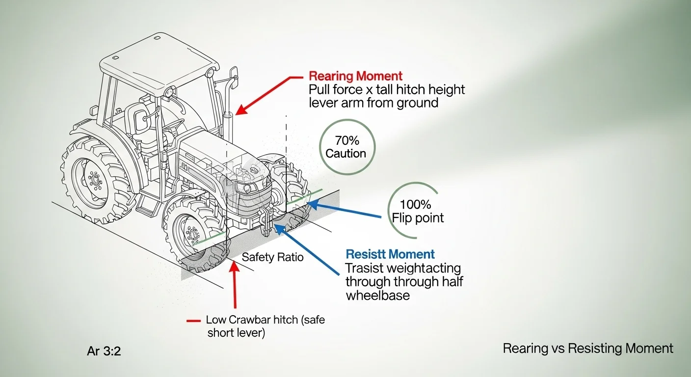

Logging winch pulls are not simply a question of whether the winch cable is rated for the load. The real limiting factor is rotational geometry: as drag force increases and hitch height rises, the rear axle of the tractor becomes a fulcrum, and the tractor itself becomes the lever. That pivot dynamic is what turns a routine skidding job into a fatal back-flip event, and it cannot be read off a winch nameplate. It requires calculating two opposing moments and comparing them directly.
This tool calculates total required pull force (accounting for log weight, surface friction, and terrain slope), the rearing moment generated at the hitch point, and the resisting moment provided by the tractor’s own weight and wheelbase. It flags when the rearing moment approaches or exceeds the resisting moment. What it does not do is substitute for a pre-operation site assessment, cable inspection, or operator training. Slope conditions at the landing may differ from conditions mid-trail, and shock loads from cable snag or clutch engagement can multiply calculated forces by a factor of three or more.
After running your numbers, you will know whether your hitch attachment height is mechanically safe for the log mass you intend to skid, and exactly how much margin you have before the rear axle becomes a pivot point.
Use the Tool
Log Skidding Winch Pull Capacity & Tractor Flip Angle
Calculate safe winch load, drag force, and tractor rearing/back-flip risk — The Yield Grid
| Log Weight (lbs) | Drag Force (lbs) | 36″ Hitch — Rearing | 4,500 lb Tractor — Safety |
|---|
How This Calculator Works — Formula & Assumptions
Step-by-step calculation:
Key assumptions: Log is dragged flat on the ground (not lifted). Tractor weight is static operating weight. Friction coefficients are typical averages. Rear axle is assumed as the primary pivot/fulcrum. Wheelbase is front-to-rear axle center distance. This tool does not account for dynamic shock loads, cable angle, or choker placement.
Critical Safety Note: Never attach a winch cable to a 3-point top link, loader bucket, or any point above the recommended drawbar height. The higher the attachment point, the greater the lever arm and rearing moment. Always use a ROPS-equipped tractor for log skidding operations.
Assumptions & Limits of This Tool
- Log is assumed to be skidded (dragged) on the ground — not lifted or suspended.
- Friction coefficients are field estimates; actual values vary with soil moisture, bark condition, and root obstacles.
- Slope is assumed uniform along the entire skid trail — real terrain may vary.
- Tractor weight is static; dynamic shock loads (dropped clutch, cable snap) can multiply forces by 3–5×.
- Choker chain breaking strength and cable rated capacity must be independently verified against manufacturer specifications.
- This tool does not account for offset pulls, cable angle deviation, or multi-log bunches.
- ROPS (Roll Over Protection Structure) is assumed to be present. Never operate without ROPS when skidding logs.
- Results assume flat or moderate terrain; steep sidehills increase rollover risk significantly and are not modeled here.
- Always consult your tractor’s operator manual for rated drawbar pull and hitch point specifications.
Before entering values, have these ready: the tractor’s gross operating weight from the operator manual (not curb weight), an estimated log weight based on species and volume, the slope angle of the skid trail in degrees, the measured height of your cable or chain attachment point from the ground, and your tractor’s front-to-rear axle centerline distance. If you are unsure how to estimate the load your 3-point hitch or loader frame can safely carry independently of logging, the 3-point lift capacity calculator covers that geometry separately.
Quick Start (60 Seconds)
- Tractor Weight (lbs): Use gross operating weight, including ballast, fluids, and any front weights. Dry curb weight understates your resisting moment and will make results appear safer than they are.
- Log Weight (lbs): Estimate using species density and log volume. Hardwoods like oak run approximately 60 lbs per cubic foot; softwoods like pine run approximately 35 lbs per cubic foot. When in doubt, round up.
- Terrain Slope (degrees): Measure the skid trail angle, not the average field slope. A 15-degree trail is notably steeper than it looks walking it. Use a smartphone inclinometer app or a hand level for accuracy.
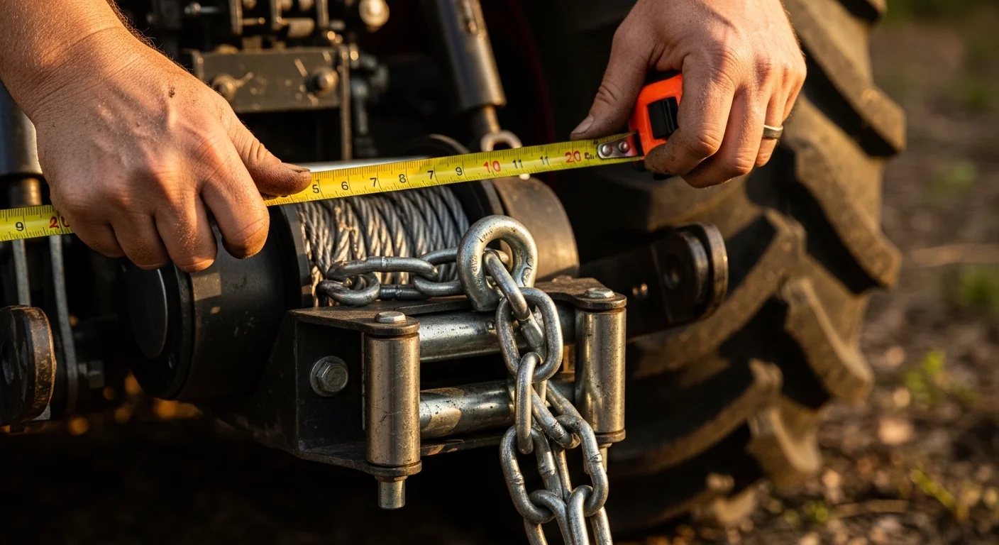
- Hitch Height (inches): Measure from level ground to the actual connection point of your chain, cable, or clevis pin. Drawbar connections sit near 18-24 inches on most compact tractors. Three-point top-link connections can exceed 48-60 inches. This single input has the largest effect on flip risk.
- Wheelbase (inches): Measure center-to-center between front and rear axles. Longer wheelbase means greater resisting moment. Do not use overall tractor length.
- Skid Surface Type: Choose the surface that best matches the majority of the drag path. Wet clay and mud significantly reduce friction, requiring less pull force but providing less traction control.
- Run the calculation before attaching the cable. If the safety ratio enters the caution zone, adjust your attachment height before you hook up, not after the log is moving.
Inputs and Outputs (What Each Field Means)
| Field | Unit | What It Represents | Common Entry Mistake | Safe Entry Guidance |
|---|---|---|---|---|
| Tractor Weight | lbs | Total operating weight providing the resisting moment against rearing | Using listed shipping weight instead of ballasted operating weight | Include front weights, rear wheel ballast water, and full fuel tank. See the tractor tire ballast calculator for ballast estimates. |
| Log Weight | lbs | Full weight of the log being dragged; determines both drag force and slope resistance | Underestimating weight of hardwoods, especially when wet | Add 10-15 lbs per cubic foot for water-saturated hardwood in wet conditions |
| Terrain Slope | degrees | Angle of the skid trail; adds a gravity-along-slope component to required pull | Measuring average field slope rather than actual trail grade | Measure at the steepest section of the trail, not the average |
| Hitch / Cable Height | inches | Vertical distance from ground to the cable attachment point; the primary lever arm for rearing moment | Measuring to the winch drum rather than to where the cable leaves the tractor frame or hitch | Measure to the actual anchor point: clevis pin, hook, or chain wrap point |
| Wheelbase | inches | Front-to-rear axle center distance; determines the moment arm resisting rearing | Using overall tractor length instead of axle centerline distance | Consult the operator manual specification page; axle-to-axle is always shorter than bumper-to-hitch |
| Skid Surface Type | dimensionless | Sets the friction coefficient (mu) that determines drag resistance as a fraction of log weight | Choosing dry dirt when the trail has leaf litter, wet moss, or stream crossings | Choose the most slippery surface condition present on the trail |
| Total Pull Force (output) | lbs | Minimum winch cable rated load required to complete the drag on the given terrain | Comparing this to winch manufacturer peak (not continuous) rating | Use continuous-rated load capacity, not peak stall force, when spec-matching |
| Safety Ratio (output) | dimensionless ratio | Rearing moment divided by resisting moment; values at or above 1.0 indicate back-flip conditions | Treating any value below 1.0 as automatically safe without reviewing hitch height | Keep ratio below 0.70 for routine operations; anything above triggers a mandatory equipment review |
Worked Examples (Real Numbers)
Scenario 1: Compact Tractor, Pine Log, Gentle Slope
- Tractor weight: 3,500 lbs
- Log weight: 800 lbs (pine, approximately 35 lbs/ft3)
- Slope: 5 degrees
- Hitch height: 20 inches (standard drawbar)
- Wheelbase: 72 inches
- Surface: Dirt (mu = 0.60)
Result: Drag Force = 480 lbs. Slope component = 70 lbs. Total pull required = 550 lbs. Rearing moment = 917 ft-lbs. Resisting moment = 10,500 ft-lbs. Safety ratio = 0.09.
This is a textbook low-risk configuration. The drawbar attachment point keeps the rearing moment well under the resisting moment. A 1,500-lb-rated winch cable handles this load with margin.
Scenario 2: Mid-Size Tractor, Large Oak Log, Moderate Slope
- Tractor weight: 5,200 lbs
- Log weight: 2,800 lbs (oak, approximately 60 lbs/ft3)
- Slope: 12 degrees
- Hitch height: 42 inches (rear frame mount)
- Wheelbase: 84 inches
- Surface: Dirt (mu = 0.60)
Result: Drag Force = 1,680 lbs. Slope component = 582 lbs. Total pull required = 2,262 lbs. Rearing moment = 7,917 ft-lbs. Resisting moment = 18,200 ft-lbs. Safety ratio = 0.44.
Within safe operating range despite the heavy hardwood and 12-degree grade, because the tractor mass and wheelbase provide substantial resisting moment. However, a 3,000-lb-rated cable minimum is needed for this pull, and the operator should engage smoothly to avoid shock-load multiplication.
Scenario 3: The Back-Flip Scenario (High Hitch on a Slope)
- Tractor weight: 4,000 lbs
- Log weight: 3,500 lbs (large oak, estimated)
- Slope: 15 degrees
- Hitch height: 60 inches (3-point top link)
- Wheelbase: 74 inches
- Surface: Dirt (mu = 0.60)
Result: Drag Force = 2,100 lbs. Slope component = 906 lbs. Total pull required = 3,006 lbs. Rearing moment = 15,030 ft-lbs. Resisting moment = 12,333 ft-lbs. Safety ratio = 1.22.
This configuration exceeds the flip threshold. The rearing moment is larger than the resisting moment, meaning the tractor will attempt to rotate backward around the rear axle the moment the winch cable loads up. Lowering the attachment to the drawbar (20 inches) reduces the rearing moment to 5,010 ft-lbs, dropping the safety ratio to 0.41 and returning the operation to a manageable range.
Reference Table (Fast Lookup)
The table below uses a standard 4,500-lb tractor with an 84-inch wheelbase, a 36-inch hitch attachment height, dirt surface (mu = 0.60), and a 10-degree slope. The resisting moment for this tractor is 15,750 ft-lbs across all rows.
| Log Weight (lbs) | Drag Force (lbs) | Slope Component at 10 deg (lbs) | Total Pull Required (lbs) | Rearing Moment at 36 in (ft-lbs) | Safety Ratio | Status |
|---|---|---|---|---|---|---|
| 500 | 300 | 87 | 387 | 1,161 | 0.07 | Safe |
| 800 | 480 | 139 | 619 | 1,857 | 0.12 | Safe |
| 1,200 | 720 | 208 | 928 | 2,784 | 0.18 | Safe |
| 1,800 | 1,080 | 312 | 1,392 | 4,176 | 0.27 | Safe |
| 2,500 | 1,500 | 434 | 1,934 | 5,802 | 0.37 | Safe |
| 3,000 | 1,800 | 521 | 2,321 | 6,963 | 0.44 | Safe |
| 4,000 | 2,400 | 694 | 3,094 | 9,282 | 0.59 | Safe |
| 5,000 | 3,000 | 868 | 3,868 | 11,604 | 0.74 | Caution |
| 6,500 | 3,900 | 1,128 | 5,028 | 15,084 | 0.96 | Caution |
| 7,000 | 4,200 | 1,215 | 5,415 | 16,245 | 1.03 | Back-Flip Danger |
This table demonstrates that a 4,500-lb tractor pulling at a 36-inch hitch height reaches the caution zone at approximately 5,000 lbs of log weight on a 10-degree grade, and crosses the flip threshold above 6,800 lbs. On a flat grade, both thresholds shift significantly higher. Changing attachment height to 20 inches (drawbar) would push the caution threshold above 9,000 lbs for the same tractor.
How the Calculation Works (Formula + Assumptions)

Show the calculation steps
Step 1: Drag Force
Drag Force (lbs) = Log Weight (lbs) x Friction Coefficient (mu)
The friction coefficient is a surface-specific constant. Dirt/bare soil uses 0.60. This represents the horizontal force required to slide the log across the surface at constant speed, ignoring slope.
Step 2: Slope Component
Slope Component (lbs) = Log Weight (lbs) x sin(Slope in degrees)
On any incline above zero degrees, gravity acts along the slope surface, adding to the winch load. At 10 degrees, sin(10) = 0.1736, meaning a 2,000-lb log adds approximately 347 lbs of slope resistance on top of its friction load.
Step 3: Total Pull Force
Total Pull (lbs) = Drag Force + Slope Component
This is the minimum continuous pull force the winch cable must sustain. Rated capacity of the winch and cable must exceed this value under continuous load conditions, not just peak stall.
Step 4: Rearing Moment
Rearing Moment (ft-lbs) = Total Pull Force (lbs) x Hitch Height (inches) / 12
The hitch height, converted to feet, is the vertical lever arm acting around the rear axle fulcrum. Doubling the hitch height exactly doubles the rearing moment. This is why top-link and loader-frame attachment points are so hazardous: they multiply the rotational force on the tractor frame in direct proportion to their height.
Step 5: Resisting Moment
Resisting Moment (ft-lbs) = Tractor Weight (lbs) x (Wheelbase (inches) / 2) / 12
The tractor’s weight, acting at the midpoint of the wheelbase, resists the rearing rotation. Half the wheelbase (in feet) is the moment arm. A longer wheelbase provides a larger resisting moment, which is why articulated and long-chassis tractors are more inherently stable for log skidding than short-chassis compact tractors.
Step 6: Safety Ratio
Safety Ratio = Rearing Moment / Resisting Moment
At 0.70 the tool enters caution zone. At 1.00 the tractor’s own weight can no longer resist the rearing moment and a back-flip event is mechanically inevitable given full cable load. Rounding: all intermediate values rounded to nearest whole pound or whole ft-lb for display; the safety ratio is displayed to two decimal places.
Unit conversions: Hitch height input is in inches, converted to feet by dividing by 12. Wheelbase input is in inches; half-wheelbase is computed internally and also converted to feet by dividing by 12. Slope is input in degrees; the calculator applies the sine function internally (no conversion needed by the user).
Assumptions and Limits
- The log is dragged flat on the ground surface, not lifted or partially suspended. Any lift of the log nose changes the effective drag geometry.
- Tractor weight is treated as a static value. Dynamic effects from clutch engagement, cable snag, or uneven terrain are not modeled. Shock loads in real field conditions can multiply instantaneous pull forces by 3 or more.
- The friction coefficient is a single-surface average. Real skid trails often cross multiple surface types (dry soil, creek crossings, leaf litter) that can shift mu significantly.
- Slope is assumed uniform along the entire drag path. Sections of variable grade require the steepest section value to be used.
- The resisting moment model assumes the tractor is on flat ground parallel to the pull direction. Sidehill operations introduce a lateral component this model does not calculate.
- Cable angle is assumed to be horizontal. Angled cable runs (e.g., pulling uphill through a snatch block) change the effective vertical and horizontal components of the load.
- This tool does not check choker chain or cable breaking strength. Those must be verified against manufacturer rated working load limit specifications independently.
- ROPS equipment is assumed present. This tool does not substitute for rollover protection hardware.
Standards, Safety Checks, and “Secret Sauce” Warnings
Critical Warnings
- The “High-Hitch Back-Flip” is mechanically instantaneous. When the rearing moment exceeds the resisting moment, tractor rotation does not happen gradually; cable tension builds during clutch engagement and releases the full rotational energy at once. Operators have reported back-flip events completing in under two seconds from initial movement. There is no recovery window once it begins.
- The three-point top link is not a winch anchor point under any load. The top-link pin location on most compact and utility tractors sits between 48 and 62 inches from the ground. At those lever arm lengths, a 1,500-lb drag force generates a rearing moment that exceeds the resisting moment of virtually every tractor under 8,000 lbs operating weight. The drawbar or a dedicated arch/skidding cone is the only acceptable attachment location for skidding loads. The tractor loader lift capacity reference explains why loader frames share this same geometric vulnerability under horizontal loads.
- Slope multiplies risk nonlinearly. At 5 degrees, the slope component adds roughly 9 lbs of force per 100 lbs of log. At 20 degrees, that increases to 34 lbs per 100 lbs. The compounding effect of slope plus hitch height plus log weight is what produces the sudden threshold crossings visible in the reference table above.
- Winch stall force is not operating rating. Many 3-point winches are marketed with a peak stall force figure, which can be double or more the safe continuous working load. The pull force calculated here is a continuous load, not an instantaneous spike.
Minimum Standards
- Attach all skidding loads at the lowest practical point on the tractor, ideally the rated drawbar, never above the top-link receiver pin.
- Verify the winch cable rated working load limit against the calculated total pull force before connecting. Grade 70 transport chain and synthetic winch ropes have specific working load limits that must be cross-checked against your result.
- ROPS must be present and intact. A back-flip event on a tractor without a roll bar or roll cage is nearly always fatal.
- Never operate within the caution zone (safety ratio above 0.70) without reducing log weight, lowering the hitch point, or both.
Competitor Trap: Most winch sizing guides found online and in dealer literature focus exclusively on cable pull rating versus log weight. They tell you whether the cable is strong enough for the load. None of them calculate the rotational moment the load creates at the attachment point relative to the tractor’s resisting weight and wheelbase geometry. That omission is what makes landowner logging a statistically dangerous activity compared to professional forestry operations, where skidder and forwarder geometry is engineered specifically around the attachment height problem. The drawbar-to-rear-axle relationship is the variable that kills operators, not cable breaking strength.
If you are working in tighter terrain where tractor maneuverability limits your approach angle, understanding your machine’s geometry through tools like the tractor turning radius calculator can help you plan skid trail entry and exit points that avoid high-angle cable pulls.
Common Mistakes and Fixes
Mistake: Using the Winch Rated Pull as the Only Safety Check
A winch rated for 4,000 lbs of pull does not tell you whether the tractor will remain on the ground while producing that pull. The winch rating addresses cable and gear capacity; it has no relationship to the tractor’s rotational stability. Two completely separate calculations are required, and most operators only perform one. The fix is to always compute the safety ratio as a mandatory pre-operation step, independent of cable capacity verification.
Mistake: Anchoring the Cable to the Three-Point Top Link or Loader Arms
The top-link receiver and loader arm pivot pins are structurally strong, which leads operators to treat them as valid winch points. The problem is geometric, not structural: their height creates a lever arm that overwhelms the tractor’s resisting moment at loads well below what the hardware can hold. A chain attached to the loader frame that is mechanically sound will still lever the tractor backward if the log is heavy enough. The fix is to route all skidding cables to the rated drawbar or to a purpose-built logging arch that lowers the effective hitch point closer to the rear axle centerline. For context on how draft force distributes along a tractor’s pull system, the box blade draft force reference illustrates how rear-mounted implements interact with drawbar geometry.
Mistake: Treating the Friction Coefficient as a Constant
Selecting “dirt” at 0.60 and leaving it there regardless of actual trail conditions introduces compounding error. A wet clay or muddy trail (mu = 0.45) actually reduces required pull force but drastically reduces traction, changing the risk profile in a different direction: the log may start moving faster than anticipated, and the tractor may lose directional control on the wet surface. The fix is to re-run the calculation with the worst-case friction coefficient for the worst section of the trail, not the average.
Mistake: Ignoring Log Weight Variation by Species and Moisture
A green (freshly felled) hardwood log can weigh 20 to 30 lbs per cubic foot more than a seasoned log of the same dimensions. An operator who sized their winch setup for dry pine and is now pulling a green oak of similar apparent volume may be doubling the actual load. The fix is to weigh representative sections using a hanging scale, or to use conservative species-specific density tables and add a moisture factor for freshly felled material. Understanding how PTO shaft torque ratings relate to sustained load is a parallel reminder that nameplate specs assume known, consistent loads.
Mistake: Calculating for the Easiest Section of the Trail
Operators often measure slope at the landing where the tractor sits, which is typically the flattest point of the operation. The actual steep sections occur mid-trail where the log is being pulled uphill through standing timber. Using a low slope value when the trail peaks at 15 or 20 degrees mid-route produces a safety ratio that is optimistic by a significant margin. The fix is to walk the full trail, identify the steepest contiguous section longer than the log length, and use that angle for all calculations.
Next Steps in Your Workflow
Once your safety ratio confirms the operation is within range, the next priority is matching your calculated pull force to actual winch and cable specifications. The total pull force output gives you the minimum continuous rated capacity required. For PTO-driven hydraulic winches, this connects directly to available drawbar pull, which depends on engine power, gear selection, and rolling resistance at the rear wheels. The drawbar horsepower calculator lets you work backward from available power to confirm your tractor can sustain the required pull under load without stalling mid-trail.
Trail preparation is the other critical step that most operators skip. A straight skid path reduces cable angle deviation, which the model assumes is zero. Any lateral angle in the cable run adds a side-load component to the rear axle that the safety ratio calculation does not capture. For operations on slopes where sidehill exposure is unavoidable, reviewing your tractor’s weight distribution with front ballast can shift the effective center of gravity forward, slightly improving the resisting moment. That relationship is covered in detail in the subsoiler HP requirements reference, which discusses how rear-mounted load affects tractor stability under sustained draft conditions.
FAQ
What is the maximum safe log weight for a 4,500-lb tractor using a 36-inch drawbar hitch?
On flat ground with a standard dirt surface, a 4,500-lb tractor with an 84-inch wheelbase stays below the 0.70 caution threshold up to approximately 4,500 lbs of log weight at a 36-inch hitch. Add a 10-degree slope and that threshold drops to near 5,000 lbs. These are not universal limits; your specific wheelbase and exact hitch height will shift the figures. Run the calculator with your actual specs.
Does the hitch height really matter that much compared to log weight?
Yes, and the relationship is direct and linear. Every inch of additional hitch height adds proportionally to the rearing moment. Moving from a 24-inch drawbar height to a 48-inch top-link connection doubles the rearing moment for the same log and terrain. Log weight and slope increase the absolute force, but hitch height controls how much of that force becomes a rotational threat to the tractor.
Can I use this calculator for a skidding arch or logging cone attachment?
Yes, but enter the actual connection height from the arch’s tow ring or clevis to the ground, not the height of the arch itself. A properly built skidding arch holds the log nose elevated while keeping the connection point low, which is exactly the geometric advantage that makes arches safer than direct cable pulls. A well-positioned arch can reduce effective hitch height to under 20 inches on some designs.
What friction coefficient should I use for a rocky forest floor with leaf litter?
Leaf litter over rocky ground creates variable friction conditions. A conservative approach uses 0.55 to 0.65 for this surface. If the leaves are wet and decomposing, the lower end is more accurate. Rocky ground alone (without leaf cover) runs closer to 0.70 due to the log’s tendency to catch on protrusions. When in doubt, select the surface type with the higher friction coefficient to err toward higher required pull force in your calculation.
My 3-point winch is rated for 6,000 lbs. Can I pull a 4,000-lb log on a 15-degree slope?
The winch rating alone does not answer that question. You also need to know your hitch height, wheelbase, and tractor weight to determine whether the rearing moment stays within safe limits. A 6,000-lb-rated winch attached at 54 inches of height on a 3,800-lb tractor pulling a 4,000-lb log on a 15-degree slope will very likely produce a safety ratio above 1.0 regardless of the cable rating. Enter your specific values into the calculator.
What is the difference between the rearing moment and the resisting moment in plain terms?
The rearing moment is the rotational force trying to tip the tractor backward, measured as pull force multiplied by attachment height. The resisting moment is the tractor’s weight pushing down through its own center of gravity, measured as tractor weight multiplied by half the wheelbase. When rearing moment exceeds resisting moment, the rear axle acts as a pivot and the tractor tips backward. The safety ratio tells you how close to that crossover point you are operating.
Conclusion
Tractor logging winch capacity is not a single number on a cable spool or a specification table in a dealer brochure. It is determined by the interaction between pull force, attachment height, tractor mass, and wheelbase geometry at the moment of loading. Every operation that uses a hitch point above the drawbar without computing the rearing-to-resisting moment ratio is operating on assumption rather than calculation. The reference table above makes clear how quickly a routine-looking setup crosses into the caution zone as log weight increases, and how the high-hitch scenario pushes that crossover to much lower load thresholds.
The single most common preventable mistake in landowner log skidding is using the three-point top link or loader frame as a convenience anchor point because it is “right there.” That decision trades a few minutes of rigging adjustment for a rearing moment that can exceed the tractor’s resisting capacity at loads well within the cable’s rated strength. Before the next operation, run your actual numbers. If you also need to verify how your tractor’s rear hydraulics interact with three-point-mounted equipment weight, the 3-point lift capacity tool addresses that calculation directly.
Lead Data Architect
Umer Hayiat
Founder & Lead Data Architect at TheYieldGrid. I bridge the gap between complex agronomic data and practical growing, transforming verified agricultural science into accessible, mathematically precise tools and guides for serious growers.
View all tools & guides by Umer Hayiat →