Loader stall and seal failure rarely happen without warning signs in the math. Before a cylinder seal fails or a hose blows, the hydraulic system reaches a predictable pressure ceiling: the relief valve setting. At that ceiling, the loader stops moving and the fluid pressure is dumped back into the reservoir. The sequence that determines whether that happens starts with cylinder bore diameter, system PSI, and the mechanical leverage geometry of the lift and curl arms. Skipping that math is why tractor owners end up frustrated with a loader that won’t rip a stump and then damaged equipment after they tried to force it.
This tool calculates theoretical breakout force and lift force for a front-end loader hydraulic cylinder based on your system’s actual inputs. It does not account for tipping stability, which is governed by the tractor’s center of gravity and rear ballast weight, not hydraulic force. It also does not calculate rod-side (retract) force, which is lower because the piston rod displaces part of the cross-sectional area. For context on how front-end loader capacity relates to the rear of the tractor, the 3-point lift capacity calculator covers the rear hitch hydraulic circuit separately, which operates under a different pressure path on most utility tractors.
After running your numbers, you will know whether your payload is within safe hydraulic range, whether a shock load (stump, rock, frozen ground) could momentarily spike the system into relief valve territory, and whether any PSI modification you are considering is genuinely safe or catastrophically risky.
Use the Tool

| PSI | Bore (in) | Cyl Area (sq in) | Raw Force (lbs) | Breakout @ 1.3 Curl (lbs) |
|---|
How This Calculator Works
This tool calculates the theoretical breakout force your front-end loader can exert at the bucket, and compares it to your payload weight to predict whether the hydraulic relief valve will open (stall).
Formula Steps:
Breakout force uses the curl ratio because the bucket curl cylinder produces the prying/breakout motion. Lift force uses the lift ratio for overhead lifting calculations.
Assumptions & Limits
This calculator uses standard hydraulic principles with the following assumptions and limitations:
- Single cylinder assumed — some loaders use two parallel lift cylinders. If yours does, the actual breakout force may be up to 2× the calculated value, but leverage geometry varies per machine.
- 100% mechanical efficiency assumed — real-world friction losses in pivots, hoses, and seals typically reduce effective force by 5–15%.
- Static load only — dynamic shock loading (hitting a stump at speed) can spike cylinder pressure 2–4× above static values, massively increasing seal stress.
- Relief valve is calibrated to rated PSI — shimmed or adjusted relief valves are treated as the entered PSI but add significant failure risk beyond the formula.
- Rod-side force not calculated — this tool calculates cap-end (extend) force only. Retract (rod-side) force is lower due to rod cross-section area.
- Tipping stability not included — rated lift capacity is always limited by machine tipping stability, which is typically far below the theoretical hydraulic breakout force for compact tractors.
The “Shimming the Relief Valve” Risk — Why It Fails
Increasing the relief valve setting raises the maximum system pressure. While the breakout force increases linearly, seal and hose stress increases exponentially:
- A standard rubber hose rated for 3,000 PSI working pressure has a 4:1 safety factor at that rating. At 3,700 PSI (shim of 700 PSI), you are operating at roughly 123% of rated pressure — eroding the entire safety margin.
- O-ring seals are sized for rated pressure. Excess pressure causes extrusion past the seal groove, resulting in sudden, high-velocity fluid release — a hydraulic injection injury risk.
- The weakest link is rarely the relief valve spring — it’s the oldest hose fitting, a crimped ferrule already fatigued by vibration.
- Shimming does not increase tipping capacity or loader structural strength — you may break the machine before you move the stump.
- Recommended fix: Use a bucket tooth bar (Piranha type) to concentrate force on a smaller area, dramatically increasing effective penetration without increasing PSI.
Before you calculate, gather these four things: your tractor’s hydraulic system pressure from the operator manual or spec sheet (not the relief valve setting on the valve body, which may have drifted), the cylinder bore diameter measured inside the barrel, the lever-arm geometry ratios for both lift and curl from the loader frame diagram, and the actual weight of what you plan to lift or break out. If you do not know the payload weight, a full bucket of wet gravel runs approximately 3,200 pounds per cubic yard; a similar volume of fresh snow is typically 600 to 900 pounds per cubic yard. For a quick cross-reference on how bucket volume translates to payload weight, see the bucket capacity calculator to estimate volume-based loads before entering them here.
Quick Start (60 Seconds)
- System PSI: Use the rated hydraulic system pressure from your tractor’s spec sheet, typically 1,800 to 3,000 PSI for utility tractors. Do not estimate this field; an incorrect value produces proportionally wrong force outputs across every other result.
- Bore diameter (inches): Measure the inside diameter of the hydraulic cylinder barrel, not the outside. A 0.5-inch error here changes the cylinder area by more than the error percentage because area scales as the square of the radius.
- Lift leverage ratio: This is the mechanical advantage multiplier applied at the lift arm pivot, typically between 0.7 and 1.5. Values below 1.0 mean the lift arm geometry reduces available force at the bucket; values above 1.0 amplify it.
- Curl leverage ratio: The curl cylinder operates at a different pivot geometry than the lift arm. Most compact loaders have curl ratios between 0.9 and 1.5. This ratio is used to compute breakout force specifically.
- Payload weight (lbs): Enter the weight of the material, attachment, or object you are attempting to move. This is compared to both the breakout force and the lift force to determine stall risk.
- Load type: Select the category that matches your task. “Tree stump / Root mass” applies a shock-load advisory because dynamic pressure spikes during extraction can far exceed the static calculated value. “Shimmed relief valve” activates a catastrophic failure risk warning.
- Result check: If your payload percentage reaches 80 percent of breakout force, the calculator enters a warning zone. At 100 percent or above, a relief valve stall is predicted under static loading conditions alone.
Inputs and Outputs (What Each Field Means)
| Field Name | Unit | What It Means | Common Mistake | Safe Entry Guidance |
|---|---|---|---|---|
| Hydraulic System Pressure | PSI | The maximum working pressure the pump delivers to the cylinder circuit | Confusing system pressure with relief valve setting; the valve setting may differ from rated system pressure if it has been adjusted | Use the figure from the operator manual spec sheet, not from a sticker on the valve body |
| Cylinder Bore Diameter | inches | Inside diameter of the hydraulic cylinder barrel; determines the piston face area that pressure acts upon | Measuring the outside of the cylinder barrel instead of the inner bore; OD is always larger than bore | If unknown, consult the cylinder manufacturer part number; bore size is always listed in cylinder specs |
| Lift Pivot Leverage Ratio | dimensionless | Mechanical advantage multiplier at the lift arm pivot; converts raw cylinder force to force available at the bucket for overhead lifting | Using the same ratio for lift and curl; these are separate pivot geometries on every loader | Consult the loader frame geometry diagram; some manufacturers publish this in the attachment spec sheet |
| Curl Pivot Leverage Ratio | dimensionless | Mechanical advantage multiplier at the bucket curl pivot; this governs prying or breakout force, not overhead lift | Assuming curl ratio equals lift ratio; they are almost never the same value | Curl ratio typically exceeds lift ratio on loaders designed for heavy breakout work |
| Bucket Payload Weight | lbs | The actual weight of material or object the loader must move or break free | Estimating by volume without accounting for material density; gravel and snow differ by 3x to 5x per unit volume | Weigh representative samples if density is uncertain; never assume worst case is wet gravel unless confirmed |
| Load Type | category | Classifies the task to apply appropriate advisory overlays for shock loading and equipment stress | Selecting “normal” for stump extraction, which ignores dynamic pressure spikes that occur when the root suddenly releases | If the load requires sudden impact or prying against a fixed object, always select a high-shock category |
| Breakout Force (output) | lbs | Maximum theoretical prying force at the bucket tip using the curl cylinder and its leverage ratio | Treating breakout force as the tractor’s rated lift capacity; the two numbers are not interchangeable | Compare against payload; if payload exceeds breakout force, the relief valve opens and the loader stalls |
| Lift Force at Bucket (output) | lbs | Force available for lifting loads overhead using the lift arm leverage ratio | Ignoring this figure and focusing only on breakout; a load can exceed lift force even if breakout force is adequate | Payload must be below lift force for overhead lifting to succeed independent of breakout force |
| Payload vs Breakout (output) | % of breakout | Ratio of payload weight to maximum breakout force, expressed as a percentage of capacity | Treating any value below 100 percent as equally safe; the 80 percent zone is a real caution threshold | Keep operational loads below 75 percent of breakout force to maintain margin for dynamic load spikes |
Worked Examples (Real Numbers)
Scenario 1: Compact Utility Tractor Moving Hay Bales
- System pressure: 2,000 PSI
- Bore diameter: 3.0 inches
- Lift leverage ratio: 0.85
- Curl leverage ratio: 1.1
- Payload weight: 800 lbs (three round hay bales)
- Load type: Normal
Cylinder area = 3.14159 x (1.5)^2 = 7.07 sq in. Raw force = 7.07 x 2,000 = 14,137 lbs. Lift force = 14,137 x 0.85 = 12,016 lbs. Breakout force = 14,137 x 1.1 = 15,551 lbs.
Result: Payload is 5.1% of breakout force. Lift force is more than 15x the payload.
The hydraulic system has significant capacity to spare at this payload. Stall risk is negligible. Tipping stability is the practical limiting factor at low payload percentages, not hydraulic force.
Scenario 2: Mid-Size Tractor Loading Wet Gravel
- System pressure: 2,500 PSI
- Bore diameter: 3.5 inches
- Lift leverage ratio: 0.90
- Curl leverage ratio: 1.3
- Payload weight: 2,800 lbs (approximately 0.875 cubic yards of wet gravel at 3,200 lbs/yd3)
- Load type: Wet Gravel
Cylinder area = 3.14159 x (1.75)^2 = 9.62 sq in. Raw force = 9.62 x 2,500 = 24,053 lbs. Lift force = 24,053 x 0.90 = 21,647 lbs. Breakout force = 24,053 x 1.3 = 31,269 lbs.
Result: Payload is 8.9% of breakout force and 12.9% of lift force.
Hydraulic margins are comfortable. However, at this bucket size and payload density, the tractor’s tipping stability load rating will likely be reached well before the hydraulic limit, particularly when lifting with arms extended.
Scenario 3: Stump Extraction with Shimmed Relief Valve
- System pressure: 3,200 PSI (relief valve shimmed from factory 2,500 PSI)
- Bore diameter: 3.5 inches
- Lift leverage ratio: 0.90
- Curl leverage ratio: 1.3
- Payload / resistance force: 4,500 lbs (assumed root mass resistance)
- Load type: Shimmed Relief Valve + Stump
Cylinder area = 9.62 sq in. Raw force = 9.62 x 3,200 = 30,787 lbs. Breakout force = 30,787 x 1.3 = 40,023 lbs.
Result: Payload resistance is 11.2% of theoretical breakout force. The hydraulic system appears capable.
The calculator result looks safe on paper, but the shimmed PSI exceeds standard hose working-pressure ratings, and dynamic shock spikes during sudden root release can momentarily multiply cylinder pressure by a factor of 2 to 4. At 3,200 PSI static, a 3x spike produces 9,600 PSI instantaneously, well beyond any standard compact tractor hose assembly rating.
Reference Table (Fast Lookup)
All breakout and lift force values assume curl ratio of 1.3 and lift ratio of 0.90. The “80% Safe Payload Limit” column shows the maximum payload that keeps the system below the warning threshold.
| System PSI | Bore (in) | Cylinder Area (sq in) | Raw Force (lbs) | Breakout Force @ 1.3 Curl (lbs) | Lift Force @ 0.90 (lbs) | 80% Safe Payload Limit (lbs) |
|---|---|---|---|---|---|---|
| 1,800 | 2.5 | 4.91 | 8,836 | 11,487 | 7,952 | 9,189 |
| 2,000 | 3.0 | 7.07 | 14,137 | 18,378 | 12,723 | 14,702 |
| 2,200 | 3.0 | 7.07 | 15,551 | 20,216 | 13,996 | 16,173 |
| 2,500 | 3.5 | 9.62 | 24,053 | 31,269 | 21,647 | 25,015 |
| 2,500 | 4.0 | 12.57 | 31,416 | 40,841 | 28,274 | 32,673 |
| 3,000 | 3.5 | 9.62 | 28,864 | 37,523 | 25,977 | 30,018 |
| 3,000 | 4.0 | 12.57 | 37,699 | 49,009 | 33,929 | 39,207 |
| 3,200 | 3.5 | 9.62 | 30,787 | 40,023 | 27,708 | 32,018 |
| 3,200 | 4.0 | 12.57 | 40,212 | 52,276 | 36,191 | 41,821 |
How the Calculation Works (Formula + Assumptions)
Show the calculation steps
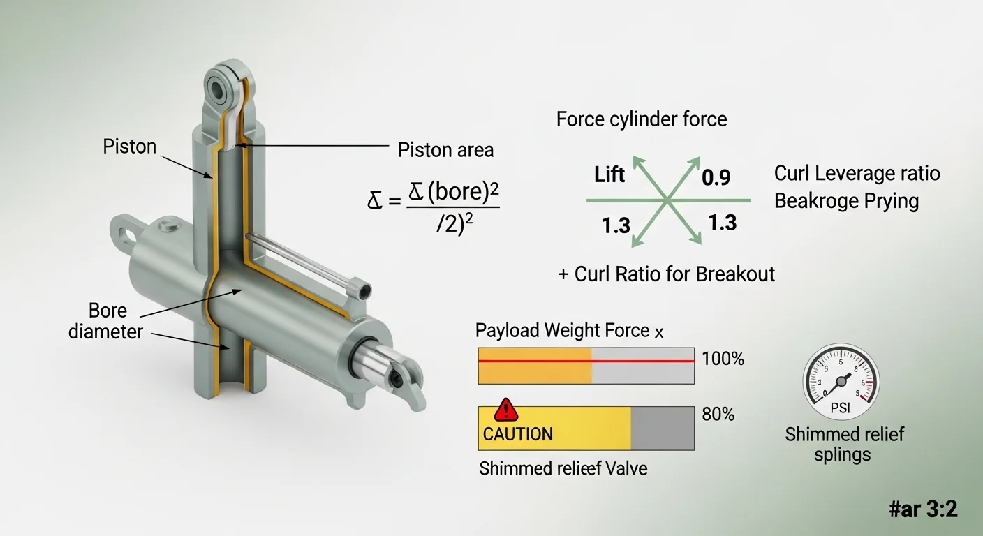
Step 1: Cylinder Area
Area (sq in) = pi x (Bore / 2)^2
This is the piston face area exposed to hydraulic pressure. Units: square inches. Pi is taken as 3.14159265. Results are rounded to two decimal places for display.
Step 2: Raw Cylinder Force
Raw Force (lbs) = Cylinder Area x System PSI
This is the theoretical maximum force the piston can exert in the extend direction (cap-end). Units: pounds. No efficiency factor is applied; real-world output is 5 to 15 percent lower due to friction and seal drag.
Step 3: Lift Force at Bucket
Lift Force (lbs) = Raw Force x Lift Leverage Ratio
The lift ratio converts cylinder force to the available force at the bucket attachment point via the lift arm pivot geometry. A ratio below 1.0 means the pivot geometry reduces force at the bucket; above 1.0 means it amplifies.
Step 4: Breakout Force
Breakout Force (lbs) = Raw Force x Curl Leverage Ratio
Breakout force uses the curl cylinder and its pivot geometry, not the lift arm. This represents the maximum prying or digging force at the cutting edge of the bucket.
Step 5: Relief Valve Check
Payload percentage = (Payload / Breakout Force) x 100
If this value equals or exceeds 100, the relief valve will open under static load. Values between 80 and 100 indicate a caution zone where dynamic load spikes are likely to trigger stall intermittently.
Assumptions and Limits
- Single cylinder assumed. Some loaders use two parallel lift cylinders. If yours does, total lift force may approach double the calculated value, though leverage geometry and synchronization affect the actual result.
- No mechanical efficiency factor applied. Friction in pivot pins, hose pressure drop, and seal drag typically reduce effective output by 5 to 15 percent compared to the theoretical value this tool returns.
- Static load only. Dynamic shock loading during stump extraction or hitting a hard obstacle can spike cylinder pressure to 2 to 4 times the static calculated value in short bursts. The calculator does not model transient pressure spikes.
- Relief valve is at rated specification. If the relief valve has been shimmed, adjusted, or has drifted from calibration, the actual relief pressure may differ from the system PSI entered. This tool treats the entered PSI as the true operating pressure.
- Rod-side force is not calculated. The retract stroke produces lower force because the piston rod cross-section reduces the effective area on that side. This tool calculates cap-end (extend) force only.
- Tipping stability is excluded. Rated loader lift capacity is always constrained by machine tipping stability, which is a function of tractor weight, wheelbase, rear ballast, and arm extension angle. In many compact tractors, the tipping load limit is far below the theoretical hydraulic breakout force.
- Leverage ratios must be measured or sourced from manufacturer documentation. Estimated ratios introduce proportional error into every output. A 10 percent error in the curl ratio produces a 10 percent error in the breakout force result.
Standards, Safety Checks, and “Secret Sauce” Warnings
Critical Warnings
- Shimming the relief valve is a documented cause of explosive hose failure. Adding a metal shim behind the relief valve spring raises the maximum system pressure. A 700 PSI increase over a 2,500 PSI rated system brings operating pressure to 3,200 PSI. Standard hydraulic hose assemblies carry a 4:1 safety factor at rated working pressure. At 3,200 PSI on a 2,500 PSI rated circuit, that margin is consumed. A fatigue crack in one ferrule crimp is now an explosive event, not a slow leak.
- Shock loads during stump extraction are not equivalent to static payload weight. When a root mass suddenly releases, the stored elastic energy in the implement and tractor frame returns to the cylinder as a pressure spike. This transient can reach 2 to 4 times the static cylinder pressure in milliseconds, which is why seals fail during stump work even when the calculated static force appears safe. The fix is not more PSI; it is concentrating force on a smaller contact area using a bucket tooth bar.
- Loader lift capacity ratings from the manufacturer already include a safety factor. Using the theoretical hydraulic breakout force from this calculator as a substitute for the manufacturer’s rated lift capacity is incorrect. The rated capacity includes stability, structural, and safety margin deductions that the hydraulic math alone does not capture.
- Operating above 3,000 PSI on a system not rated for it voids predictable failure modes. Components manufactured to a 2,500 PSI working pressure specification have unknown remaining margin at 3,200 PSI. Failure can occur at a hose, a fitting, a cylinder port, or a valve body without warning.
Minimum Standards
- Keep operational payload below 80 percent of calculated breakout force to maintain margin for unexpected dynamic load spikes during normal operation.
- Verify hydraulic hose and fitting pressure ratings against actual system PSI before any task involving high shock loads. If the hose assembly date code is older than 5 years, replace it before high-stress work regardless of visible condition.
- Use a calibrated hydraulic pressure gauge installed at the cylinder port to verify actual system pressure at load. Relief valve settings drift over time and may not match the nameplate or spec sheet value.
- Check tractor rear axle weight and ballast configuration before relying on breakout force calculations for heavy tasks. If the tractor can tip, it will tip before the relief valve opens.
Competitor Trap: Most online breakout force calculators stop at the math and declare the lift “safe” if payload is below breakout force. They omit three things that determine whether the hydraulic system actually survives the job: dynamic shock load multipliers for high-impact tasks, the difference between breakout force and tipping stability limits, and the compounding risk of a shimmed or drifted relief valve. A number that looks safe in static math can be a hose failure waiting to happen under real working conditions. Understanding how shock torque works in other hydraulic implement circuits illustrates why transient forces are the dominant failure mode in high-load tractor hydraulics, not steady-state pressure.
If your tractor’s available rear ballast is uncertain, the tire ballast calculator can help you determine how much weight is on the rear axle at any given front loader load, which directly affects when tipping stability becomes the binding constraint rather than hydraulic force.
Common Mistakes and Fixes
Mistake: Measuring Bore from the Outside of the Cylinder
The outside diameter of a hydraulic cylinder barrel is always larger than the bore (inside diameter) due to wall thickness. Since cylinder area scales as the square of the radius, even a half-inch measurement error produces a disproportionately large error in force output. A 3.5-inch bore and a 4.0-inch barrel OD are not the same input. Fix: Obtain the cylinder bore from the manufacturer part number, spec sheet, or by direct inside measurement with a bore gauge.
Mistake: Using the Relief Valve Setting Instead of System Pressure
The hydraulic system pressure and the relief valve setting are related but not identical. On many tractors, the relief valve is set slightly above system pressure to allow the pump to maintain continuous flow. If the relief valve has been shimmed or adjusted upward, it no longer represents the designed operating pressure ceiling. Entering the shimmed relief valve setting as “system pressure” inflates the calculated force and creates a false sense of safety. Fix: Use the factory-rated system pressure from the operator manual; test with a calibrated gauge if there is any doubt.
Mistake: Treating Breakout Force as the Loader’s Rated Lift Capacity
Breakout force (calculated using the curl ratio) and rated lift capacity (published by the loader manufacturer) are different quantities. Rated lift capacity already incorporates stability limits, structural load limits, and safety deductions. The hydraulic breakout force can be two to four times higher than the rated lift capacity on compact tractors because the hydraulic system is capable of forces the frame or tipping geometry cannot safely sustain. Other high-load calculations that follow a similar pattern can be explored through the box blade draft force calculator, which separates hydraulic capability from practical field load limits. Fix: Use this tool to understand hydraulic limits only; always cross-reference the manufacturer’s published lift capacity rating for operational load decisions.
Mistake: Ignoring the Difference Between Lift Force and Breakout Force
The curl cylinder and the lift cylinder act on different pivot geometries. A payload that clears the breakout force threshold may still exceed the lift force threshold, meaning the loader can curl the bucket but cannot raise the loaded bucket to full height. Operators frequently discover this when a full bucket of dense material curls successfully but refuses to lift past a certain height. Fix: Check both the breakout force output and the lift force output in the results panel, and compare both against your payload weight independently.
Mistake: Selecting “Normal” Load Type for Stump and Embedded Rock Work
The static breakout force calculation does not capture the transient pressure spikes that occur when a root mass or embedded rock suddenly releases. Selecting “Normal” for this type of work bypasses the shock load advisory in the tool and leads operators to trust a static math result for a dynamic loading condition. Repeated high-shock cycles without a safety margin accelerate seal extrusion and hose fatigue even when no single event appears to exceed capacity. Fix: Always select “Tree Stump / Root Mass” for any task involving prying against a fixed, embedded object, and plan operational payload below 65 percent of calculated breakout force for this category.
Next Steps in Your Workflow

Once you know your breakout force and its relationship to your planned payload, the next decision is whether to work within those limits or change one of the inputs. Raising system PSI is rarely the right answer; it increases stress on every component in the circuit proportionally. A more effective approach for heavy breakout tasks is reducing the effective contact area by adding a bucket tooth bar, which concentrates the same force over a fraction of the cutting-edge width. For tasks that exceed safe loader breakout force entirely, a different implement category may be more appropriate. A logging winch or drawbar-based pulling system exerts force along a completely different load path that does not stress the loader hydraulic circuit at all.
If this calculation is part of planning a broader high-load operation, consider checking your tractor’s available tractive effort and engine output to confirm the powertrain can actually deliver the hydraulic flow the system demands under sustained load. The drawbar horsepower calculator gives a complementary view of what the tractor can sustain at the drawbar, which indirectly reflects available hydraulic pump power at working engine RPM.
FAQ
What is breakout force on a front-end loader?
Breakout force is the maximum theoretical prying or digging force the loader bucket can exert at its cutting edge, generated by the curl cylinder working through the bucket pivot geometry. It is distinct from lift force, which describes the ability to raise a loaded bucket overhead. Breakout force is always calculated using the curl leverage ratio, not the lift arm ratio.
Why does my loader stall even when the payload seems within range?
Static calculations assume ideal conditions: steady pressure, no friction loss, accurate leverage ratios, and a perfectly calibrated relief valve. In practice, mechanical efficiency losses of 5 to 15 percent, dynamic load spikes, and a relief valve that has drifted below its nominal setting can all reduce the effective working threshold below the calculated value. The calculator reports theoretical maximums, not guaranteed field performance.
How do I find my tractor’s hydraulic system pressure?
The most reliable source is the tractor operator manual under “Hydraulic Specifications.” Many manufacturers also publish this in the technical service manual. If neither is available, a calibrated hydraulic pressure gauge installed at the remote outlet or cylinder port with the loader stalled against a solid stop will show the actual relief pressure, which is the practical system ceiling.
What is the leverage ratio and where do I find it?
The leverage ratio is the mechanical advantage coefficient between the hydraulic cylinder extension and the force delivered at the bucket pivot point. It is determined by the physical dimensions of the loader frame arms and cylinder mounting points. Some manufacturers publish this figure in attachment specification sheets; otherwise it can be derived from a geometric diagram of the loader frame by dividing the cylinder moment arm by the bucket pivot moment arm.
Can I increase loader breakout force by increasing tire ballast?
Tire ballast increases rear axle weight and shifts the tractor’s stability threshold, which means the machine can resist tipping at higher loader loads. This allows you to work closer to the hydraulic breakout force limit without the tractor lifting at the rear. However, it does not change the hydraulic breakout force itself; that is determined by PSI, bore diameter, and leverage geometry.
What is the difference between breakout force and rated lift capacity?
Rated lift capacity is the manufacturer’s published safe working load, which already incorporates stability limits, structural safety factors, and operational deductions. Hydraulic breakout force is a theoretical ceiling derived from cylinder geometry and system pressure alone. Breakout force often significantly exceeds rated lift capacity on compact tractors because the hydraulic system is more capable than the frame and stability geometry can safely exploit.
Conclusion
Hydraulic breakout force math produces a number that is useful only when it is paired with the failure modes that number does not capture: shock load transients, mechanical efficiency losses, tipping stability limits, and the compounding risk of modified relief valve settings. The core differentiator of this calculator is that it surfaces those conditions explicitly rather than producing a single “safe” or “unsafe” output without context. A static payload percentage within the breakout force limit is a necessary condition for safe operation, not a sufficient one.
The single most common and consequential mistake operators make is shimming the relief valve in response to a loader that cannot handle a specific task, then discovering that the system fails at the weakest point in the circuit under the first high-shock event. The practical alternative, concentrating breakout force over a smaller contact area using a tooth bar or appropriately sized attachment, almost always solves the actual problem without adding system pressure risk. For operations where total tractor tractive and implement capacity needs to be understood together, the subsoiler horsepower requirements calculator provides a parallel framework for matching tractor capability to high-draft implement loads.
Lead Data Architect
Umer Hayiat
Founder & Lead Data Architect at TheYieldGrid. I bridge the gap between complex agronomic data and practical growing, transforming verified agricultural science into accessible, mathematically precise tools and guides for serious growers.
View all tools & guides by Umer Hayiat →