Every tractor manufacturer publishes a 3-point hitch lift capacity number. What the spec sheet does not print is the fine print embedded in ASABE Standard S217: that rating was measured at the hitch pin ends, with the load applied exactly 24 inches behind the pin centerline. Move your implement’s center of gravity to 30 inches, 36 inches, or further back, and the leverage physics reduce your usable capacity in a straight, calculable ratio. A tractor listed at 1,500 lbs of lift may realistically handle only 850 lbs for a given spreader or box blade. The arithmetic is not complicated, but it requires four inputs most operators never look up.
This tractor 3-point lift capacity calculator applies the ASABE leverage penalty formula and then runs a second, separate check: whether the implement’s weight and overhang will generate enough uplift force to unload the front axle entirely. The tool does not simulate hydraulic pump pressure, terrain slope, or dynamic bounce loads on rough ground. It works from static geometry at the moment of full lift on level ground, which is the exact scenario where steering loss happens most abruptly.
After running your numbers, you will know the true effective lift capacity for your implement’s actual center of gravity, and you will know whether your current front-end weight is adequate to keep the front wheels on the ground. If you already manage ballast with the tractor tire ballast calculator, the front-end weight figure you have there feeds directly into the Front End Weight field here.
Use the Tool

3-Point Hitch Lift Capacity & Front-Axle Float
Calculate your tractor’s real-world lift capacity and wheelie risk at a glance
| CG Offset | Leverage Penalty | Eff. Capacity | Uplift Force |
|---|
How This Calculator Works — Formula & Assumptions
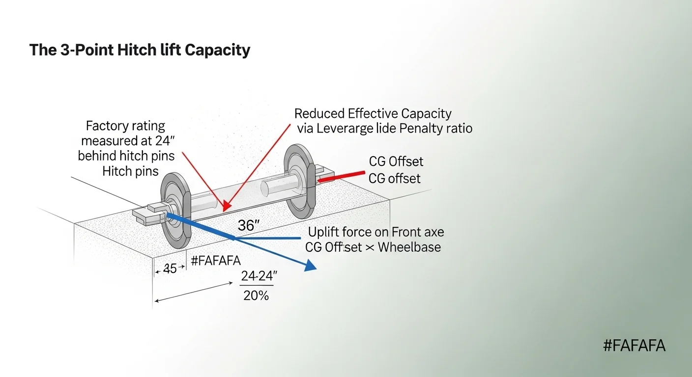
Why factory lift ratings are misleading: Tractor manufacturers rate 3-point hitch lift capacity at the hitch pins, measured exactly 24 inches behind the pin centerline. But most real implements — spreaders, tillers, balers — have their center of gravity 24 to 36+ inches behind the pins. This acts as a lever arm, dramatically reducing your effective lift capacity.
24 ÷ Actual CG Offset (inches)If your implement’s CG is 36″ behind pins: Penalty = 24 ÷ 36 = 0.667 (33% capacity loss)
Factory Lift Capacity × Leverage PenaltyExample: 1,500 lbs × 0.667 = 1,001 lbs effective
(Implement Weight × CG Offset) ÷ WheelbaseThis is the force the implement applies trying to lift your front wheels off the ground
Uplift Force > Front End Weight → WHEELIE WARNINGFront Weight Margin =
Front End Weight − Uplift ForceNegative margin means the implement is a steering/safety hazard
Assumptions & Limits:
- Factory lift capacity is per ASABE/SAE standards measured at the lower hitch pin ends, 24″ behind pin centerline.
- CG offset is measured from the hitch pin centerline to the implement’s loaded center of mass.
- Wheelbase is measured axle center to axle center on level ground.
- Front-end weight should include tractor front ballast, loader if attached, and any suitcase weights.
- This calculator does not account for dynamic loading (bouncing over terrain), hills, or hydraulic pump limitations.
- Always follow your tractor manufacturer’s published safety guidelines and never exceed rated capacities.
- Category 1 pins are rated for tractors up to ~50 HP; Category 2 for 50–150 HP; Category 3 for 150+ HP.
The “Factory Rating Trap” — What Every Farmer Needs to Know
Real-world scenario: A farmer buys a 1,200 lb fertilizer spreader for a tractor rated to lift “1,500 lbs.” They fill it up to 1,400 lbs loaded, lift the hitch, and the tractor’s front wheels instantly pop off the ground — complete loss of steering at road speed.
Why it happened: The 1,500 lb rating was at 24″ behind pins. The loaded spreader’s CG was 36″ back. The effective capacity was only 1,000 lbs. But more critically, the 1,400 lb implement × 36″ ÷ 72″ wheelbase = 700 lbs of uplift force — exceeding the 600 lb front axle weight. The tractor wheeled.
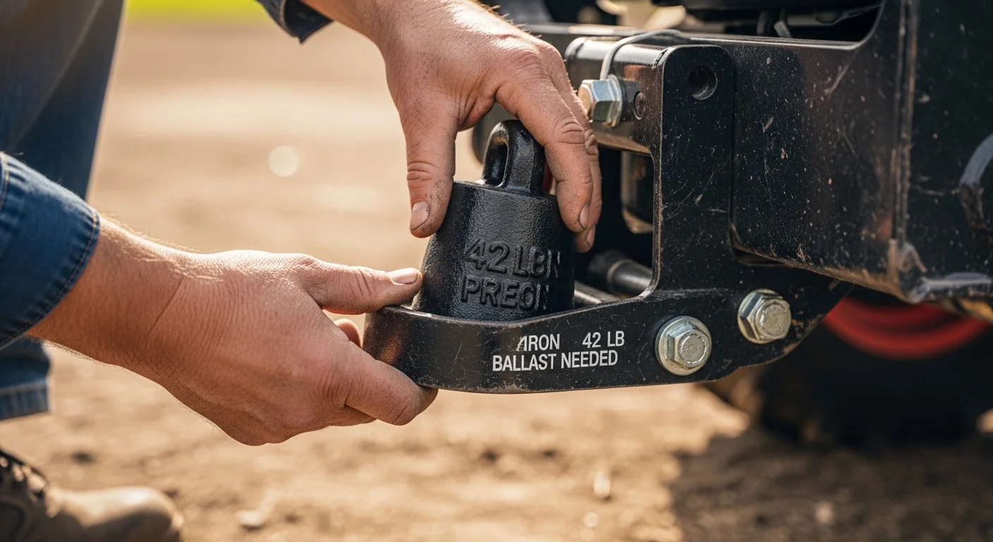
The fix: Adding 4×42 lb front suitcase weights (168 lbs) brought front axle weight to 768 lbs — a 68 lb safety margin. This tool shows you exactly how many pounds of front ballast you need before you ever hitch up a heavy implement.
Before you enter numbers, gather three documents: your tractor's operator manual or specification sheet (for factory lift capacity and wheelbase), the implement's product spec sheet or shipping weight tag, and an estimate of how far the implement's loaded center of gravity sits behind the hitch pins. Have all values in pounds and inches. If your tractor also carries a front-end loader, note that loader lift capacity is governed by different leverage geometry than the 3-point system, but the loader's weight does count toward your total front axle weight figure.
Enter all five fields before clicking Calculate. The tool will not run a partial result. If you are unsure of the implement's CG offset, a conservative default for compact implements like box blades and tillers is 24 inches; for large spreaders and seeders with long frames, 36 to 48 inches is more realistic.
Quick Start (60 Seconds)
- Factory Lift Capacity at Pins: Find this in your tractor spec sheet under "3-point hitch lift capacity." Use the published number in pounds. Do not substitute loader capacity or drawbar pull figures.
- Implement Weight: Use loaded weight if you plan to lift the implement while it is loaded (spreaders, seeders, sprayer tanks). Empty weight applies only if the implement is always lifted empty.
- CG Offset Behind Pins: Estimate the horizontal distance from the hitch pin centerline to the point where most of the implement's mass is concentrated. For a compact tiller, this is typically 18 to 24 inches. For a three-point mounted fertilizer spreader filled to capacity, it can reach 36 to 48 inches.
- Wheelbase: Measure axle center to axle center along the tractor's frame, or find it in the operator manual. Typical compact utility tractors run 60 to 78 inches; larger row-crop tractors range from 88 to 110 inches.
- Front End Weight: Include the tractor's natural front weight distribution plus any suitcase weights, ballast blocks, or the mass of a front-end loader if attached. A loader frame and arms alone can add 600 to 1,000 lbs over the front axle without a bucket load.
- Do not mix metric and imperial inputs. The tool uses inches and pounds throughout.
- If you receive a wheelie warning, the Ballast Needed output tells you the minimum additional front weight required. Round up to the nearest standard suitcase weight increment before ordering.
Inputs and Outputs (What Each Field Means)
| Field | Unit | What It Measures | Common Entry Mistake | Safe Entry Guidance |
|---|---|---|---|---|
| Factory Lift Capacity at Pins | lbs | The manufacturer's published lift rating measured at the hitch pin ends under ASABE S217 conditions (load applied 24" behind pins, level, static) | Using a "maximum lift" marketing figure rather than the ASABE-rated pin capacity from the spec table | Find the value labeled "3-point lift" or "Category lift" in the operator manual specifications section |
| Implement Weight | lbs | Total weight of the implement as it will be lifted, including any material load (seed, fertilizer, gravel) | Using dry/empty weight for an implement that is always lifted while loaded | Use loaded weight for any implement that carries material; add soil or mud accumulation for a safety buffer |
| CG Offset Behind Pins | inches | Horizontal distance from the hitch pin centerline to the implement's center of mass when mounted and loaded | Defaulting to 24" for all implements, or measuring to the rear edge instead of the center of mass | For symmetrical implements, measure to the midpoint of the frame; for front-heavy implements, bias the estimate forward of center |
| Tractor Wheelbase | inches | Distance between front and rear axle centerlines, which sets the lever arm for the front-axle uplift calculation | Measuring to the outside of a tire rather than axle center, or using a ballpark estimate | Use the spec sheet value; or measure with a tape between the two axle center marks on a hard surface |
| Front End Weight | lbs | Total weight acting on the front axle: factory front weight distribution plus any added ballast, weights, or loader frame mass | Ignoring the loader frame and arms, which are always present even without a bucket load | Use the tractor's listed front axle weight from the spec sheet, then add any suitcase weight or ballast block mass |
| Output: Effective Lift Capacity | lbs | The actual usable lift capacity for your implement's CG position, after the leverage penalty is applied | Assuming this equals factory capacity | If this number is below implement weight, the hitch is mechanically overstressed regardless of wheelie risk |
| Output: Uplift Force | lbs | The force the implement exerts trying to lift the front axle off the ground, based on its weight and overhang relative to wheelbase | Ignoring this value and relying only on the lift capacity check | This must remain below front-end weight for safe steering |
| Output: Front Weight Margin | lbs | The cushion between your front-end weight and the uplift force. A negative number is a steering-loss condition. | Treating any positive margin as unconditionally safe, ignoring dynamic loading over rough terrain | A minimum positive margin of 150 lbs is a reasonable conservative target on level ground; increase for hillside use |
| Output: Ballast Needed | lbs | Additional front-end weight required to bring uplift force below current front-end weight. Zero when no wheelie risk exists. | Adding exactly the minimum ballast with no safety buffer | Round up to the next suitcase weight increment and add one more unit as a buffer |
If you work frequently with implements that stress the drawbar rather than the 3-point system, the drawbar horsepower calculator covers the pull-load geometry that complements the lift analysis here.
Worked Examples (Real Numbers)
Scenario 1: Compact Utility Tractor with a Garden Tiller
- Factory Lift Capacity at Pins: 1,500 lbs
- Implement Weight: 680 lbs
- CG Offset Behind Pins: 24 inches
- Tractor Wheelbase: 66 inches
- Front End Weight: 920 lbs
Leverage Penalty: 24 / 24 = 1.000
Effective Capacity: 1,500 x 1.000 = 1,500 lbs
Uplift Force: (680 x 24) / 66 = 247 lbs
Front Weight Margin: 920 - 247 = 673 lbs (positive)
Result: No warnings triggered. Implement weight is 45% of effective capacity; front axle has a 673-lb margin. This is a straightforward safe combination.
When implement CG sits exactly at the ASABE reference distance of 24 inches, the factory rating applies without penalty. Any implement with a longer frame will push the CG further back and reduce usable capacity below this number.
Scenario 2: Mid-Size Tractor with a Loaded Fertilizer Spreader
- Factory Lift Capacity at Pins: 1,500 lbs
- Implement Weight: 1,200 lbs (loaded)
- CG Offset Behind Pins: 36 inches
- Tractor Wheelbase: 72 inches
- Front End Weight: 650 lbs
Leverage Penalty: 24 / 36 = 0.667
Effective Capacity: 1,500 x 0.667 = 1,000 lbs
Uplift Force: (1,200 x 36) / 72 = 600 lbs
Front Weight Margin: 650 - 600 = 50 lbs (positive, but critically thin)
Result: Effective capacity is reduced to 1,000 lbs; the 1,200-lb loaded spreader exceeds it by 200 lbs. Front axle margin is only 50 lbs, a value that vanishes over any minor terrain irregularity.
This combination exposes both failure modes: the hitch is mechanically overstressed, and the front axle is effectively unloaded. Adding even a single 42-lb suitcase weight does not solve the over-capacity problem; the implement load must be reduced, or the tractor must be upsized.
Scenario 3: Large Row-Crop Tractor with a Three-Point Box Blade
- Factory Lift Capacity at Pins: 5,800 lbs
- Implement Weight: 2,400 lbs
- CG Offset Behind Pins: 30 inches
- Tractor Wheelbase: 102 inches
- Front End Weight: 3,800 lbs
Leverage Penalty: 24 / 30 = 0.800
Effective Capacity: 5,800 x 0.800 = 4,640 lbs
Uplift Force: (2,400 x 30) / 102 = 706 lbs
Front Weight Margin: 3,800 - 706 = 3,094 lbs (generous)
Result: Implement weight is 52% of effective capacity; front axle margin is well over 3,000 lbs. Both checks pass comfortably.
Larger tractors with long wheelbases benefit significantly in the front-axle calculation: the same uplift force is divided across more distance, making wheelie risk proportionally lower than on compact tractors with short wheelbases and the same implement hanging off the rear.
Reference Table (Fast Lookup)
The table below shows effective lift capacity and front-axle uplift force for a 1,500-lb factory-rated tractor at several common CG offsets and implement weights, assuming a 72-inch wheelbase. Use it for quick pre-purchase checks before pulling out a full calculator run.
| CG Offset (in) | Leverage Penalty | Effective Capacity (lbs) | Implement at 800 lbs: Uplift (lbs) | Implement at 1,200 lbs: Uplift (lbs) | Minimum Front Wt to Match 1,200-lb Uplift |
|---|---|---|---|---|---|
| 18 | 1.333 | 2,000 | 200 | 300 | 300 lbs |
| 24 | 1.000 | 1,500 | 267 | 400 | 400 lbs |
| 28 | 0.857 | 1,286 | 311 | 467 | 467 lbs |
| 30 | 0.800 | 1,200 | 333 | 500 | 500 lbs |
| 36 | 0.667 | 1,000 | 400 | 600 | 600 lbs |
| 42 | 0.571 | 857 | 467 | 700 | 700 lbs |
| 48 | 0.500 | 750 | 533 | 800 | 800 lbs |
| 60 | 0.400 | 600 | 667 | 1,000 | 1,000 lbs |
All values assume a 72-inch wheelbase and 1,500-lb factory lift rating. Effective capacity values below the implement weight at that row represent a mechanically over-stressed hitch condition, separate from the wheelie risk shown in the uplift columns.
How the Calculation Works (Formula + Assumptions)
Show the calculation steps
Step 1: Leverage Penalty
Leverage Penalty = 24 / Actual CG Offset (inches)
The ASABE standard anchors the factory rating at 24 inches. Any CG further back reduces the usable capacity by this ratio. A CG at 36 inches produces a penalty of 0.667. A CG at 48 inches produces 0.500. CG positions closer than 24 inches produce a penalty above 1.000, meaning the tractor can technically lift more than the standard rating at that position, though the hydraulic system's pressure limit may cap actual lift below the computed value.
Step 2: Effective Lift Capacity
Effective Capacity = Factory Lift Capacity x Leverage Penalty
Result in pounds, rounded to the nearest whole pound. This is the maximum implement weight the 3-point system can handle at the specified CG offset under static, level conditions.
Step 3: Uplift Force on the Front Axle
Uplift Force = (Implement Weight x CG Offset) / Wheelbase
This treats the rear axle as a fulcrum. The implement's weight, acting at its CG offset distance, applies a moment that is resisted by the front axle. Dividing the moment by wheelbase converts it to a front-axle lift force in pounds. Rounding to the nearest whole pound.
Step 4: Wheelie Risk Check
If Uplift Force is greater than Front End Weight, the net load on the front axle is negative, meaning the tractor tips backward. Front Weight Margin = Front End Weight minus Uplift Force. A negative margin is a wheelie condition. Ballast Needed = the absolute value of the margin, rounded up to the next whole pound.
Assumptions and Limits
- Factory lift capacity is assumed to comply with ASABE S217, measured at the lower link attachment ends with the load at 24 inches behind pin centerline on level ground. If your manufacturer uses a different standard or measures at the ball ends rather than pin ends, the calculation will be optimistic.
- CG offset is measured as a horizontal distance on level ground. On slopes, the effective overhang changes with pitch angle; this tool does not model slope effects.
- The uplift force formula assumes static loading. Dynamic bounce over rough terrain, abrupt hydraulic lowering, or hitting an obstacle while the implement is raised can multiply actual forces significantly beyond the static calculation.
- Hydraulic system pressure limits are not modeled. Some tractors will stall the hydraulic pump before reaching the geometric lift limit, effectively capping usable capacity below the calculated figure.
- The tool assumes a rigid, non-articulated tractor. Articulated or row-crop tractors with pivot steering have different rear-axle geometry that may alter actual uplift force distribution.
- CG offset is user-supplied and is the highest source of error in the calculation. Loaded CG shifts forward or backward as material moves during operation; worst-case (fully rearward) CG should be used for safety calculations.
- Hitch pin category ratings (Category 1, 2, 3) define pin diameter and strength but do not override the geometric capacity limits computed here. A Category 2 pin on an undersized tractor does not expand the tractor's lift rating.
Standards, Safety Checks, and "Secret Sauce" Warnings
Critical Warnings
- The 24-inch measurement trap: ASABE S217 pins the factory rating exactly at 24 inches behind the hitch pin ends. Every inch the implement's CG moves beyond that point reduces effective capacity by the ratio 24/CG. At 48 inches, the tractor lifts only half its stated capacity. This is not a malfunction; it is basic lever physics that the spec sheet omits.
- Steering loss is instantaneous: When uplift force exceeds front axle weight, the front wheels do not gradually lighten. They come off the ground as a unit the moment the hitch is raised, removing all steering response at the same instant. At road transport speed, this is a rollover precursor, not a controllable condition.
- Loaded vs. empty weight mismatch: An implement weighed empty at 600 lbs can load to 1,800 lbs with dense fertilizer or wet soil, tripling the uplift force. Always calculate with the heaviest realistic operating weight, not the shipping or dry weight.
- Front-loader frames count as front ballast and as added stress: A loader frame over the front axle adds weight (good for the wheelie check), but it also shifts the tractor's dynamic balance. Operators who remove the loader for a season and add the same equivalent suitcase weights maintain equivalent static balance; those who simply remove the loader without compensating lose significant front weight.
Minimum Standards
- Maintain a positive front-axle weight margin at all times. A minimum of 150 lbs of margin on level ground is a reasonable conservative floor; ROPS-certified operation on slopes requires higher margins per individual manufacturer guidance.
- Do not exceed the computed effective lift capacity. The hitch linkage, top link, and Category pins are loaded in bending and tension simultaneously; operating above effective capacity stresses these components beyond the design point even if the tractor can physically raise the load.
- Category 1 pins are suited for tractors with factory lift ratings up to approximately 2,200 lbs. Category 2 pins are appropriate for ratings from roughly 1,500 to 7,700 lbs. Use heavy-duty Category 1/2 drawbar pins rated for your actual lift capacity, not the cheapest aftermarket equivalent. Check the PTO shaft sizing calculator alongside this tool when matching a new implement, since PTO torque capacity and hitch capacity should both be verified against the tractor's ratings before first operation.
Competitor trap: Most pages covering tractor 3-point lift capacity either quote the factory number without adjustment or list a generic "reduce by 20% for safety" rule of thumb. Neither approach is correct. The leverage penalty is a deterministic calculation, not a blanket discount. An implement with its CG at 24 inches carries no penalty at all; one at 48 inches carries a 50% penalty. Applying a fixed 20% discount to both is simultaneously too conservative for the shorter implement and dangerously insufficient for the longer one. Use the formula; skip the rule of thumb.
Operators who regularly work with heavy three-point implements also benefit from reviewing the box blade draft force calculator, which addresses the separate but related question of how much traction and drawbar force a box blade demands during grading passes.
Common Mistakes and Fixes
Mistake: Using the Implement's Shipping Weight
Shipping weight reflects the implement as it leaves the factory, often without ballast, fluid, or material load. A pull-type spreader that ships at 450 lbs can weigh 1,400 lbs loaded with lime. Entering the shipping weight produces a result that looks safe while the real operating condition is well into wheelie territory. Fix: Always calculate with the maximum operating weight, including the heaviest material you will ever load.
Mistake: Treating the Factory Rating as the Operating Limit
Operators read "1,500 lb 3-point capacity" and shop for implements up to 1,490 lbs without considering CG offset. An implement at 1,490 lbs with a 36-inch CG places 1,490 lbs against an effective capacity of 1,000 lbs on that tractor, stressing the hitch by 49%. This is the most common source of bent or cracked top links and damaged Category pin bores. Fix: Always apply the leverage penalty before comparing implement weight to capacity.
Mistake: Ignoring the Front-Axle Uplift Check
Even when effective capacity math looks fine, the uplift force calculation is a second, independent failure mode. A 900-lb implement at 48 inches on a short-wheelbase tractor can generate more uplift force than the front axle weight, even though 900 lbs is well within the tractor's listed 1,500-lb capacity. The two checks address different physics and both must pass. Fix: Run both computations; do not stop at the capacity check.
Mistake: Measuring Wheelbase to the Outside of the Tire
The uplift formula uses the distance between axle centerlines, not outer tire edges. A tractor with 18-inch-wide rear tires measured to the outside produces a wheelbase figure 9 inches longer than the correct axle-to-axle measurement. That error understates uplift force and gives a false sense of margin. Fix: Measure between the axle center bolt or spindle center on each side, or pull the exact figure from the operator manual specification table.
Mistake: Adding Ballast Only to the Minimum Computed Value
The Ballast Needed output is the break-even point: it brings front-axle weight exactly equal to uplift force, which is a zero-margin condition with no buffer for terrain dips, acceleration, or load shift. Adding that exact number and stopping there leaves no engineering margin. Fix: Round up to the next suitcase weight increment and add at least one additional weight unit as a practical safety buffer.
Mistake: Forgetting That Removing a Loader Removes Ballast
Front-end loaders, even when empty, add several hundred pounds over the front axle. Operators who remove the loader in summer to mount a rear implement often do not replace that front weight with suitcase weights, dramatically reducing front-axle load for the exact type of operation that generates the most uplift force. Fix: Re-run this calculator any time a loader is removed. Replace its front-axle weight contribution with suitcase weights sized to the calculated ballast requirement for your heaviest rear implement.
Next Steps in Your Workflow
Once you have confirmed that effective lift capacity exceeds implement weight and that front-axle margin is positive, the next practical question is whether the rest of the tractor-implement pairing is correct. A matched implement means not only that the hitch can lift it, but that the tractor has enough power and ground engagement for the work. The rotary cutter size calculator walks through a similar matching exercise for PTO-driven cutting implements, where blade width and horsepower are the binding constraints rather than hitch geometry.
If your calculation revealed a wheelie risk that requires significant ballast, it is also worth reviewing your overall front-to-rear weight distribution in a seasonal context. Tractors used for both winter work and summer tillage often need a formal front ballasting strategy rather than a case-by-case weight addition. The tractor turning radius calculator becomes relevant here too, because heavy front ballast affects steering effort and minimum turn radius on compact tractors with short wheelbases.
FAQ
Does the 3-point hitch lift capacity change if I lower the implement instead of keeping it fully raised?
The ASABE S217 rating and the leverage penalty formula both apply at full lift height. As the implement is lowered, the effective geometry shifts and the hydraulic pressure required to hold position changes, but the static uplift-force calculation used here is most critical at or near full lift, which is the condition that produces maximum front-axle unloading.
My tractor manual lists both a "pin" capacity and a "ball end" capacity. Which do I use?
Use the pin capacity. Ball-end measurements include the extra lever arm added by the lower link ball, which adds distance and further reduces effective capacity. Using the pin figure gives you the baseline that the leverage penalty formula adjusts correctly. Using the ball-end figure would understate the penalty you need to apply.
Can a quick hitch change my effective lift capacity?
A quick hitch adds a short arm that pushes the implement's attachment point further behind the tractor's hitch pins, increasing the effective CG offset by the length of the quick hitch coupling, typically 6 to 12 inches. This reduces effective capacity by that additional leverage. Add the quick hitch arm length to your CG offset estimate before calculating.
What is a realistic front-end weight for a 50-horsepower compact utility tractor without a loader?
Front axle weight on a bare compact utility tractor in the 40 to 60 HP range typically falls between 700 and 1,100 lbs depending on the manufacturer and model year. This value is listed in the operator manual as "front axle static load" or similar. Do not estimate it; use the published figure or weigh the front axle with a scale.
Is the leverage penalty formula the same for Category 1, 2, and 3 hitches?
The leverage penalty calculation is identical across all hitch categories. Category designations define pin diameter, lift arm dimensions, and pin spacing, not the underlying physics of leverage. A Category 3 hitch on a large tractor carries the same 24/CG penalty ratio as a Category 1 hitch on a compact tractor, applied to its respective factory lift rating.
How do I estimate the CG offset for an implement that came without a specification sheet?
For a symmetrical implement with a uniform cross-section, the CG offset approximates to the distance from the hitch pins to the midpoint of the implement's longitudinal length. For implements with heavy components at one end (a seed hopper at the rear of a seeder, for example), estimate the balance point by visualizing where a single lift point would hold the implement level. Err toward a longer estimate when unsure.
Conclusion
The tractor 3-point lift capacity calculator exists because the single number on a spec sheet is only accurate for a single geometric condition: a load centered exactly 24 inches behind the pin ends, on level ground, with no consideration of front-axle balance. Every real implement departs from that condition in some way, and the departure is always in the direction of reduced usable capacity and increased steering risk. The tool makes the hidden math visible in about 30 seconds.
The single most important mistake to avoid is matching implement weight to factory rated capacity without running the leverage penalty calculation. That approach consistently produces over-stressed hitches and, in the worst cases, the front-axle unloading scenario that eliminates steering at exactly the wrong moment. For operators working with heavy disc implements where per-blade weight distribution matters as much as total hitch load, the disc harrow weight per blade calculator addresses the soil penetration and frame stress side of the same implement sizing decision.
Lead Data Architect
Umer Hayiat
Founder & Lead Data Architect at TheYieldGrid. I bridge the gap between complex agronomic data and practical growing, transforming verified agricultural science into accessible, mathematically precise tools and guides for serious growers.
View all tools & guides by Umer Hayiat →