Most ventilation guides treat exhaust fan sizing as a simple volume-divided-by-time problem. That framing produces fans that move enough air on paper but ignores the two variables that actually determine whether a sealed grow tent performs correctly: static pressure from carbon filters and duct bends, and the intake area required to prevent destructive negative pressure. A fan that is slightly too large for an under-vented tent will not just pull harder; it can collapse the tent walls inward, snap structural poles, and suffocate its own motor from lack of replacement air.
This calculator determines the minimum CFM your exhaust fan must deliver after accounting for heat load from your grow lights, resistance penalties from a carbon filter, and friction losses from every 90-degree bend in your duct run. It also calculates the minimum passive intake area your tent needs so that negative pressure stays in the useful range rather than the damaging one. What it does not do: predict real-world fan performance at a specific static pressure point, account for altitude adjustments, or replace a proper HVAC load calculation for commercial grow rooms.
After running the calculator, you will know the minimum CFM to specify when shopping for an inline fan, the minimum intake opening your tent needs to avoid implosion, and whether your current duct layout is adding enough resistance to warrant a higher-rated fan than the bare volume calculation would suggest.
Use the Tool
Grow Tent Exhaust CFM Calculator
Prevent tent implosion · Size your exhaust fan correctly · Maintain negative pressure
| Scenario | CFM Needed | Status |
|---|
| Tent Size | Volume | Min CFM (no filter) | Min CFM (w/ filter) | Typical Light W |
|---|---|---|---|---|
| 2×2×4 ft | 16 cu ft | ~60 | ~73 | 200W |
| 3×3×6 ft | 54 cu ft | ~100 | ~120 | 400W |
| 4×4×6.5 ft ★ | 104 cu ft | ~165 | ~198 | 600W |
| 4×8×7 ft | 224 cu ft | ~285 | ~342 | 1000W |
| 5×9×8 ft | 360 cu ft | ~420 | ~504 | 1500W |
| 10×10×8 ft | 800 cu ft | ~800 | ~960 | 3000W |
📐 How This Calculator Works — Formula & Assumptions
This calculator follows HVAC-derived sizing principles adapted for grow tent environments. Here is the exact step-by-step math:
Air exchanges every 3 minutes for cannabis/high-transpiration plants
HeatCFM = BTU_hr ÷ (1.1 × ΔT_20°F)
Assumes 20°F temperature rise acceptable. Worst-case BTU for HPS/MH; LEDs run ~30% cooler
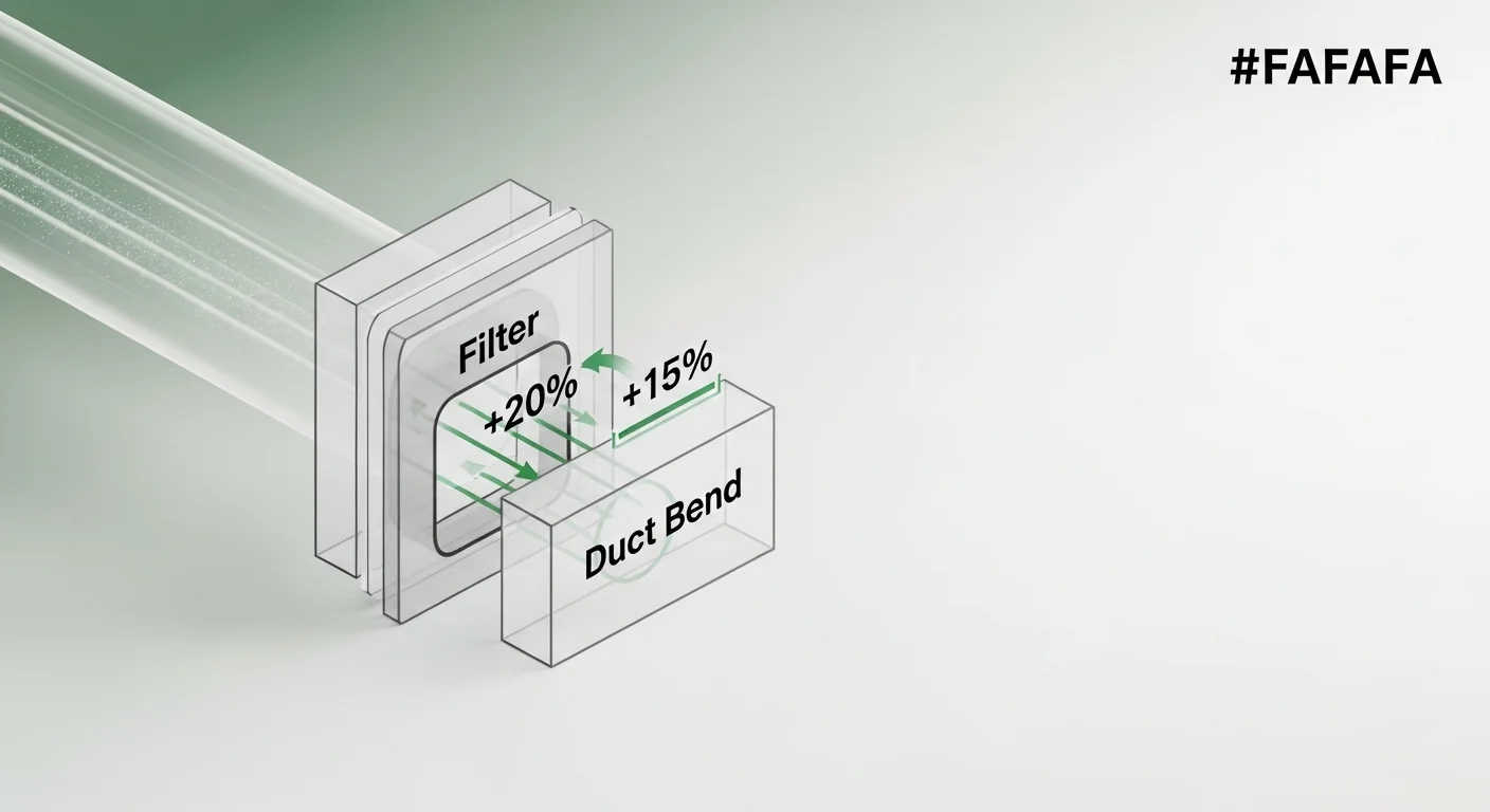
DuctingPenalty = Bends × 15%
Each 90° bend adds ~15% static pressure drop. Long straight runs add minimal resistance and are ignored here (captured in fan derating).
Round up to nearest whole number. Always size to a fan that meets or exceeds this value at its rated static pressure.
- Air exchange rate of 1 per 3 minutes is the industry standard for grow tents. Aggressive grows or hot climates may require 1–2 minute exchange rates.
- HeatCFM assumes a 20°F (11°C) temperature differential. Higher tolerances reduce this number; tighter tolerances increase it.
- LED grow lights produce approximately 30% less heat than HPS for the same output wattage. The calculator uses full wattage as a conservative worst-case assumption.
- Filter penalty of 20% is a conservative average for quality activated carbon filters. Cheap or clogged filters may restrict more.
- Each 90° bend penalty of 15% is based on ASHRAE equivalent duct length methods. Actual loss depends on bend radius and duct diameter.
- This calculator does not account for altitude, humidity load, or CO₂ enrichment. Add 10–15% buffer for hot or humid climates.
- Always purchase a fan rated higher than the calculated CFM, as manufacturer ratings are at zero static pressure. Real-world CFM is lower.
Before you start, have a tape measure handy for your tent’s interior dimensions in feet, your grow light’s rated wattage from the spec sheet (total watts drawn from the wall, not an equivalent claim), and a count of every 90-degree elbow or sharp bend in your planned duct run. If you are connecting a greenhouse exhaust system rather than a grow tent, the greenhouse fan calculator uses a similar airflow model scaled for larger structures.
Enter dimensions as decimal feet where needed (a 6-foot-6-inch ceiling is 6.5 ft). Use the actual wattage draw of your fixture, not the equivalent or advertised output. Select “Yes” for carbon filter if the filter is in-line anywhere on the exhaust path, not just directly on the fan inlet.
Quick Start (60 Seconds)
- Tent Length (ft): Measure the interior floor length, not the exterior frame. Fabric tents lose 1-2 inches to seams; measure what plants actually occupy.
- Tent Width (ft): Same principle as length. A “4×4” tent is often 3.9 feet interior. Use the actual measured value, not the marketing dimension.
- Tent Height (ft): Measure from floor to the highest point plants can reach, or to the ceiling fan mount if lower. Do not subtract hanging space; full volume matters for air exchange.
- Grow Light Wattage (W): Enter total actual wall watts for all fixtures combined. For LED panels, use the manufacturer’s “actual power draw” specification, not the HPS-equivalent claim. If running two 300W-draw LEDs, enter 600.
- Ducting Length (ft): Count total duct footage from the fan inlet to where air exits the space, including both tent-side and room-side runs. Long runs above 20 feet warrant a booster fan regardless of CFM rating.
- 90-Degree Bends: Count every elbow. A 45-degree bend counts as roughly half a 90-degree bend; round up. Four or more 90-degree bends in a single run is where airflow restriction becomes a design problem, not just a penalty.
- Carbon Filter: Select “Yes” if any carbon filter sits anywhere on the exhaust circuit. A pre-filter wrap on its own does not count; an in-line carbon canister does.
Inputs and Outputs (What Each Field Means)
| Field | Unit | What It Represents | Common Mistake | Safe Entry Guidance |
|---|---|---|---|---|
| Tent Length | feet | Interior floor length used to calculate enclosure volume | Using the label size (e.g., “4×4”) instead of measuring the actual interior | Measure with a tape; use decimals (e.g., 3.9) |
| Tent Width | feet | Interior floor width | Same as length; marketed sizes are usually the frame, not interior | Measure both walls; use the smaller value if tapered |
| Tent Height | feet | Interior vertical clearance; drives total volume calculation | Measuring to the roof peak when a fan mount lowers the effective ceiling | Measure to the lowest overhead obstruction in the plant zone |
| Grow Light Wattage | watts | Total electrical power consumed by all lighting; drives heat load CFM | Entering LED “equivalent” wattage (e.g., 600W equivalent) instead of actual draw (e.g., 300W) | Check the spec sheet for “power consumption” or measure with a kill-a-watt meter |
| Ducting Length | feet | Total straight duct footage on the exhaust path; long runs add system resistance | Measuring only the tent-exit leg and ignoring the run to the exterior | Add all segments including inside and outside the tent |
| 90-Degree Bends | count | Number of sharp direction changes; each adds a 15% CFM penalty | Ignoring bends because “it’s just flexible duct” — flex duct bends restrict more than rigid elbows | Walk the planned duct path and count every turn tighter than 45 degrees as a full bend |
| Carbon Filter | Yes / No | Indicates whether a carbon canister is in-line, adding 20% resistance | Selecting “No” because the filter is at the fan inlet, not realizing it still restricts airflow | Select “Yes” any time a carbon canister is on the exhaust circuit, regardless of position |
| Required CFM (output) | CFM | Minimum fan rating needed to meet air exchange and heat removal goals | Ordering a fan rated exactly at this number; real-world CFM under load is lower | Purchase a fan rated at least 15% above this result at your system’s static pressure |
| Minimum Intake Area (output) | square feet / diameter | Passive vent area required to supply replacement air without causing destructive negative pressure | Assuming mesh side vents are “enough” without checking area against CFM | Calculate total open vent area and compare to the displayed requirement before zipping the tent |
For guidance specifically on sizing the carbon canister itself rather than calculating its pressure impact on fan selection, the carbon filter sizing calculator handles canister diameter and bed depth for your CFM and odor load.
Worked Examples (Real Numbers)
Example 1: Small Starter Setup (2x2x4 ft, 200W LED, No Filter)
- Length: 2 ft, Width: 2 ft, Height: 4 ft
- Tent Volume: 2 x 2 x 4 = 16 ft³
- Grow Light Wattage: 200W actual draw
- Carbon Filter: No
- Ducting Length: 6 ft, Bends: 1
Base CFM = 16 / 3 = 5.3 CFM
Heat Load = (200 x 3.41) / (1.1 x 20) = 682 / 22 = 31.0 CFM
Bend Penalty = 1 x 15% = 15%
Total = (5.3 + 31.0) x (1 + 0.15) = 36.3 x 1.15 = 41.7 CFM
Result: 42 CFM minimum. A 4-inch inline fan rated at 50-60 CFM handles this setup with appropriate headroom. The heat load dominates because the tent volume is small relative to light power, a pattern common in 2×2 setups.
Example 2: Standard 4×4 with HPS and Carbon Filter (4x4x6.5 ft, 600W, Filter On, 2 Bends)
- Length: 4 ft, Width: 4 ft, Height: 6.5 ft
- Tent Volume: 4 x 4 x 6.5 = 104 ft³
- Grow Light Wattage: 600W
- Carbon Filter: Yes (+20%)
- Ducting Length: 10 ft, Bends: 2
Base CFM = 104 / 3 = 34.7 CFM
Heat Load = (600 x 3.41) / 22 = 2046 / 22 = 93.0 CFM
Penalty = 20% (filter) + 30% (2 bends) = 50%
Total = (34.7 + 93.0) x 1.50 = 127.7 x 1.50 = 191.5 CFM
Result: 192 CFM minimum. A 6-inch fan rated at 220-250 CFM is appropriate. Note that without the filter and bends, the bare number would be 128 CFM — a grower who skips the penalty math and buys a 150 CFM fan ends up chronically undersized.
Example 3: Large Multi-Light Tent (5x9x8 ft, 1500W, Filter On, 4 Bends)
- Length: 5 ft, Width: 9 ft, Height: 8 ft
- Tent Volume: 5 x 9 x 8 = 360 ft³
- Grow Light Wattage: 1500W combined
- Carbon Filter: Yes (+20%)
- Ducting Length: 18 ft, Bends: 4
Base CFM = 360 / 3 = 120 CFM
Heat Load = (1500 x 3.41) / 22 = 5115 / 22 = 232.5 CFM
Penalty = 20% (filter) + 60% (4 bends) = 80%
Total = (120 + 232.5) x 1.80 = 352.5 x 1.80 = 634.5 CFM
Result: 635 CFM minimum. At this level, a single 8-inch fan rated at 750+ CFM is appropriate, or two 6-inch fans in parallel. With 4 bends at 80% combined penalty, rerouting even one bend saves roughly 53 CFM of required capacity — equivalent to dropping from an 8-inch to a slightly smaller unit.
Reference Table (Fast Lookup)
| Tent Size (ft) | Volume (ft³) | Base CFM (no penalties) | Heat CFM at Typical Watts | Total CFM (filter + 2 bends) | Recommended Fan Size | Min Intake Opening |
|---|---|---|---|---|---|---|
| 2x2x4 | 16 | 5 | 31 (200W) | 55 | 4-inch, 60+ CFM | 0.38 ft² |
| 2x4x5 | 40 | 13 | 62 (400W) | 113 | 4-inch, 125+ CFM | 0.78 ft² |
| 3x3x6 | 54 | 18 | 62 (400W) | 120 | 4-inch, 130+ CFM | 0.83 ft² |
| 4x4x6.5 | 104 | 35 | 93 (600W) | 192 | 6-inch, 200+ CFM | 1.33 ft² |
| 4x8x7 | 224 | 75 | 155 (1000W) | 345 | 6-inch, 350+ CFM | 2.40 ft² |
| 5x5x8 | 200 | 67 | 155 (1000W) | 330 | 6-inch, 350+ CFM | 2.29 ft² |
| 5x9x8 | 360 | 120 | 233 (1500W) | 531 | 8-inch, 550+ CFM | 3.69 ft² |
| 8x8x8 | 512 | 171 | 311 (2000W) | 726 | 8-inch, 750+ CFM | 5.04 ft² |
| 10x10x8 | 800 | 267 | 466 (3000W) | 1100 | 10-inch, 1100+ CFM | 7.64 ft² |
Total CFM column assumes carbon filter (20%) plus two 90-degree bends (30%). Minimum intake opening is calculated as Total CFM divided by 144 to convert to square feet. All fan recommendations include the 15% headroom buffer above the calculated minimum.
How the Calculation Works (Formula + Assumptions)
Show the calculation steps
Step 1: Tent Volume
Volume = Length x Width x Height (all in feet, result in cubic feet)
Step 2: Base CFM (Air Exchange Rate)
Base CFM = Volume / 3
This targets one complete air exchange every 3 minutes, which is the standard rate for high-transpiration crops. The divisor changes the exchange interval: Volume / 1 gives one exchange per minute for aggressive hot climates; Volume / 5 is the minimum acceptable for cool, dry setups.
Step 3: Heat Load CFM
BTU per hour = Watts x 3.41 (the thermal equivalency factor for electrical energy)
Heat CFM = BTU_per_hour / (1.1 x 20)
The 1.1 factor comes from the sensible heat constant for air at standard conditions. The 20 is the assumed acceptable temperature rise in degrees Fahrenheit. A 20 degree F rise (roughly 11 degrees C) means the exhausted air is 20 degrees warmer than incoming air. If your ambient room runs hot already and you want a tighter rise of 10 degrees F, double the Heat CFM value before proceeding.
Step 4: Resistance Penalties
Carbon filter penalty: add 20% to the combined (Base + Heat) CFM
Each 90-degree bend: add 15% per bend
Total penalty multiplier = 1 + 0.20 (if filter) + (bends x 0.15)
Step 5: Total Required CFM
Total = (Base CFM + Heat CFM) x Total Penalty Multiplier
Result is rounded up to the nearest whole CFM. This is the minimum at which a fan must perform under your actual system resistance, not the fan’s free-air rating.
Rounding rule: Always round up (ceiling). A fan specified at 191.2 CFM should be replaced with one rated at 192 CFM minimum, then further buffered upward for real-world derating.
Assumptions and Limits
- The 3-minute air exchange rate is appropriate for cannabis and other high-transpiration crops. Seedling rooms, cloning chambers, or cooler setups may tolerate a 4-5 minute exchange; adjust manually by using a shorter interval in your volume calculation.
- The 20-degree F temperature differential is a conservative midpoint. In a climate-controlled room where incoming air is already conditioned, this differential may be acceptable at 15 degrees. In a hot garage or attic space in summer, it may need to drop to 10 degrees, which doubles the heat load CFM output.
- LED fixtures are assumed to emit full wattage as heat. In practice, quality quantum board LEDs convert roughly 40-50% of input power to usable photons rather than heat. Using full wattage is conservative and safe; if you have manufacturer thermal data showing a lower heat fraction, you may reduce the wattage input by that fraction.
- The 15% bend penalty is based on ASHRAE equivalent duct length methods for smooth rigid elbows. Flexible aluminum duct kinked at a 90-degree angle produces higher losses, sometimes 20-25%. The calculator is conservative for rigid duct; it may underestimate losses for kinked flex duct.
- Straight duct run length contributes friction loss but at a much lower rate than bends. Runs under 25 feet contribute losses smaller than the inherent uncertainty in manufacturer CFM ratings, so they are captured in the recommended purchase buffer rather than a separate formula term.
- The tool does not account for altitude. At 5,000 feet elevation, air density is roughly 17% lower, meaning your fan moves the same volume but with less mass, reducing heat transfer capacity. Add 10-15% to your calculated CFM if growing above 3,500 feet.
- CO2 enrichment systems in sealed rooms require different airflow logic; this calculator is designed for negative-pressure tents exchanging air with the room, not sealed recirculation setups.
Standards, Safety Checks, and “Secret Sauce” Warnings

Critical Warnings
- Tent implosion is a mechanical failure, not just reduced airflow. When exhaust capacity significantly exceeds available intake area, the pressure differential across the tent fabric becomes structurally damaging. Tent walls snap inward, poles can buckle, and plants in the path of collapsing fabric sustain physical damage. The minimum intake area displayed by the calculator is not a suggestion; it is the threshold below which structural failure becomes likely at fan operating speed.
- Manufacturer CFM ratings are measured at zero static pressure. No real installation has zero static pressure. With a carbon filter and two bends, a fan rated at 200 CFM may deliver 130-150 CFM under actual conditions. Always specify a fan that meets your calculated requirement at the static pressure your system actually produces, or apply a minimum 15% buffer above the free-air rated CFM when a manufacturer does not publish static pressure curves.
- A speed controller that reduces fan speed to its minimum setting can push the system into undersized territory. If you plan to run a large fan at 20-30% speed to reduce noise, verify that the delivered CFM at that setting still meets the calculated minimum. Smart controllers with tachometer feedback (such as the AC Infinity controller series) make this verification possible; basic triac dimmers do not.
- Carbon filter resistance increases as the media loads with activated carbon particles and particulate buildup. A filter that adds 20% resistance when new may add 35-40% near the end of its service life. Re-running this calculator with a higher penalty estimate toward the end of a filter’s life helps identify whether a speed increase or filter replacement is the limiting factor.
Minimum Standards
- At least one complete air exchange every 3 minutes during the lights-on period for high-transpiration crops.
- Passive intake area must equal or exceed the calculated minimum (Total CFM / 144 in square feet) to keep negative pressure in the functional range rather than the damaging range.
- Fan purchase rating should be at least 15% above the calculated Total Required CFM to account for real-world derating under static pressure.
- Duct runs with 4 or more 90-degree bends should be reviewed for rerouting; the combined 60%+ penalty at that count frequently makes fan upgrade a false economy compared to simplifying the duct path.
Competitor Trap: Many grow tent ventilation guides stop at “CFM equals tent volume divided by one to three minutes.” That formula produces a number that accounts only for air exchange and completely ignores the two largest variables in a real installation: grow light heat load and system resistance. A 4×4 tent with a 600W HPS light and a carbon filter needs roughly 190 CFM — more than 4x the bare air-exchange figure of 35 CFM. Growers who follow the simplified formula buy undersized fans, then compensate by running lights at reduced power or adding portable AC units, neither of which addresses the root calculation error.
Airflow interacts closely with humidity management. A correctly sized exhaust fan removes both heat and water vapor, but in rooms with high ambient humidity, the exhaust may not fully manage vapor pressure deficit on its own. The VPD calculator helps you determine whether your airflow is controlling the vapor pressure differential your crop stage requires, or whether a supplemental dehumidifier is necessary.
For heat load calculations that extend beyond exhaust sizing into full HVAC planning, the grow room AC sizing calculator takes the same light wattage inputs and extends them to BTU-per-hour cooling requirements for air conditioning unit selection.
Common Mistakes and Fixes
Mistake: Using LED “Equivalent” Wattage Instead of Actual Draw
A fixture marketed as “600W HPS equivalent” may draw only 250-320W from the wall. Entering 600W into the wattage field inflates the heat load CFM by a factor of nearly two, leading to an oversized fan recommendation. Conversely, using the actual low draw when lights do run hotter than their photon efficiency implies can underestimate heat. The only reliable input is the actual wall-draw wattage from the spec sheet or a power meter reading.
Fix: Check the fixture’s “power consumption” specification, not the output or equivalent claim, and use that number.
Mistake: Counting Only the Bends You Can See
Growers frequently count the elbow fittings they install deliberately — the S-curve to exit the tent port, the turn to route along the wall — and miss the incidental bends formed when flexible duct sags, kinks around a corner, or is compressed by a storage item touching the duct run. Flexible aluminum duct that bends even 45 degrees under its own weight at a low-support point creates meaningful restriction that compounds with planned bends.
Fix: Walk the full duct path after installation and add one additional bend count for every point where the duct changes direction by more than 30 degrees, regardless of whether a fitting caused it.
Mistake: Ignoring Intake Requirements After Calculating Exhaust
Exhaust CFM calculations are the first step, not the complete picture. Running a correctly sized 200 CFM exhaust fan through tent flaps with a total open mesh area of 0.5 square feet creates a pressure drop large enough to deform the tent structure. The intake constraint is the more dangerous failure mode because it is invisible until the tent walls are visibly stressed. A dehumidifier running inside the tent is not an intake substitute; it recirculates internal air and does not supply replacement fresh air.
Fix: After calculating required CFM, compute minimum intake area (CFM / 144 in square feet) and verify your open vent area against that number before running the fan at full speed. The dehumidifier sizing tool can confirm whether your airflow strategy needs supplemental dehumidification independent of the exhaust path.
Mistake: Setting the Fan Speed Controller to Maximum and Leaving It
Running any variable-speed inline fan at 100% continuously shortens motor life, increases noise significantly, and often overshoots the negative pressure target into the damaging range for tents with smaller intake vents. Conversely, setting the controller to a low speed without recalculating delivered CFM can slip below the required minimum, particularly once a carbon filter loads up and adds more resistance over time.
Fix: Set the controller to the lowest speed that maintains visible slight inward tent wall deformation (the correct indicator of functional negative pressure) and use a tachometer or smart controller’s readout to log the operating speed for future reference.
Mistake: Applying One CFM Number to Both the Filter Fan and a Booster Fan in Series
Some growers add an in-line duct booster fan mid-run to compensate for a long duct path. Placing a booster downstream of the carbon filter creates competing pressure zones and can actually reduce filter effectiveness by pulling air through the carbon bed too quickly for adequate odor adsorption. The calculator accounts for bends and filter as a single system; if a booster is in the design, the system requires a more complex analysis. Adding a grow space oscillating fan for canopy movement serves a different purpose entirely and should not be conflated with exhaust airflow; the oscillating fan sizing guide covers that selection separately.
Fix: Avoid booster fans in series with a carbon filter. Instead, reroute the duct to reduce bends, or specify a larger primary exhaust fan that can overcome the system resistance without a booster.
Next Steps in Your Workflow
Once you have your required CFM number, the immediate next step is cross-referencing it against the static pressure performance curve for any fan you are considering, not just its free-air rating. Manufacturers of quality inline fans publish “SP curves” showing CFM delivered at 0, 0.1, 0.2, 0.4, and 0.8 inches of water column static pressure. A system with a carbon filter and two bends typically operates in the 0.3-0.6 range; find the CFM at that pressure point and confirm it still meets your calculated minimum. If it does not, move to the next fan size up and repeat the check.
Ventilation is one of several interconnected climate variables. After locking in exhaust fan sizing, the next calibration point is typically CO2 management, since a correctly exhausted tent removes CO2-enriched air along with heat and humidity. The CO2 requirements calculator helps determine whether a passive CO2 source is sufficient after accounting for your air exchange rate, or whether a regulator setup is warranted. For rooms where you are also running active air conditioning rather than relying on exhaust alone, the grow light energy cost tool can help model the combined operating cost of lighting and climate equipment at your local electricity rate.
FAQ
What is CFM and why does it matter for grow tents?
CFM stands for cubic feet per minute, which measures the volume of air a fan moves in one minute. In a grow tent, CFM determines how quickly heat and humidity are removed and fresh CO2-bearing air is introduced. Too low and plants suffer heat stress; too high without adequate intake causes structural tent damage from excessive negative pressure. Matching CFM to your specific tent size, light load, and duct setup is the core of effective climate control.
What is negative pressure in a grow tent and is it always good?
Negative pressure means the air pressure inside the tent is slightly lower than outside, which keeps odors contained by ensuring air always flows inward rather than outward. A slight negative pressure is desirable. Excessive negative pressure, caused by a fan too large for the available intake area, causes tent walls to collapse inward and can starve the fan of airflow, potentially burning out the motor. The goal is just enough negative pressure to hold tent walls slightly concave, not visibly stressed or deformed.
How do carbon filters affect the fan size I need?
Carbon filters add resistance to the airflow path, which reduces the volume of air a fan can move at any given speed. This calculator applies a 20% CFM penalty when a filter is selected, meaning you need a fan rated 20% higher than the base CFM requirement to deliver the same airflow after the filter’s resistance is factored in. As filter media ages and loads up, that penalty can increase further, which is why filter replacement on schedule matters for sustained airflow performance.
Does duct length matter if I only have a few bends?
Short straight duct runs under 20-25 feet contribute friction losses smaller than the uncertainty in most fan ratings, so this calculator does not add a per-foot penalty for straight runs. Runs above 20 feet begin to accumulate meaningful friction, particularly in flexible duct. The calculator flags runs above 20 feet as a concern and recommends considering a higher-rated fan or a mid-run booster to compensate. In practice, minimizing bends produces more CFM gain than shortening straight runs.
Should I size my fan to the calculated minimum or add headroom?
Always purchase a fan rated above the calculated minimum. Manufacturer CFM ratings are measured at zero static pressure, meaning no filter, no bends, no duct. Real installations always operate at positive static pressure, which reduces actual airflow below the rated figure. A 15% buffer above the calculated minimum is the practical starting point for systems with typical resistance. For setups with heavy filter loading, 4+ bends, or runs over 25 feet, a 25-30% buffer is more appropriate.
Can I use this calculator for a grow room rather than a grow tent?
The formula works for any sealed or semi-sealed space where you are sizing an exhaust fan to control air exchange and heat removal. For grow rooms with multiple entry points, HVAC returns, or commercial dehumidification equipment, the calculation is a starting estimate rather than a precise specification. True grow room HVAC design involves latent heat load from transpiration, which varies by crop stage and canopy density and is outside the scope of this tool. For larger enclosed spaces, the calculator output is a useful sanity check against a professional HVAC load calculation.
Conclusion
The most dangerous number in grow tent ventilation is not the CFM that is too low; it is the CFM that is too high for the available intake. Growers who understand the tent implosion failure mode shop for fans differently: they calculate required intake area alongside exhaust CFM, check both before commissioning, and treat the fan speed controller as a precision instrument rather than a set-and-forget knob. The calculator here encodes that two-constraint problem — exhaust need and intake requirement — into a single output so both numbers are visible before a fan is purchased or installed.
The one mistake that costs the most is skipping the resistance penalties. A bare volume calculation may suggest 35 CFM for a 4×4 tent; the same tent with a carbon filter and a pair of duct bends actually needs 190 CFM. That gap is not a rounding error; it is the difference between an effective setup and one that either fails to exchange air or requires a fan so large it implodes the structure. For further climate control planning, the dew point calculator is the logical complement to exhaust sizing, helping you verify that your airflow strategy is keeping moisture below condensation risk thresholds in your specific temperature range.
Lead Data Architect
Umer Hayiat
Founder & Lead Data Architect at TheYieldGrid. I bridge the gap between complex agronomic data and practical growing, transforming verified agricultural science into accessible, mathematically precise tools and guides for serious growers.
View all tools & guides by Umer Hayiat →