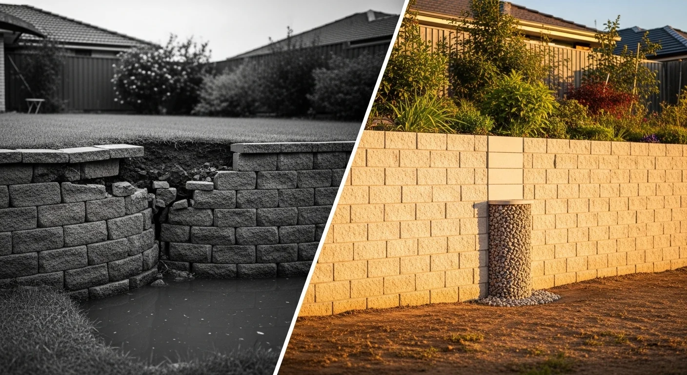
Wall builders often focus on stacking block and getting the top level. The force that tears a wall apart isn’t the weight of the soil; it’s water trapped behind the face without a path out. This calculator isolates that hidden load and turns an invisible failure mode into a number you can act on.
What you get here is a single overturning force number that combines active soil pressure, hydrostatic pressure from trapped water, and any driveway or structure load you plan to place above the wall. The tool also gives you the minimum geogrid length and the drainage base depth required to keep the wall standing year after year. It does not replace a stamped engineering plan for tall walls, but it tells you exactly when engineering is no longer optional.
Bottom line: After running the numbers, you’ll know whether your wall design can survive a saturated backfill event — the scenario most online calculators ignore. And you’ll get the drainage dimensions needed to make sure that event never happens. For a deeper dive on how soil reinforcement prevents long‑term movement, see our geogrid reinforcement calculator.
Use the Tool
[put the tool here]
Before you start, have the wall height and length on site (feet, not inches). Know your backfill material — heavy clay or sandy/gravelly fill — because that changes the pressure coefficient by nearly 50%. If you plan any driveway, patio, or structure behind the wall, note the load in pounds per square foot; the tool includes common presets. The block setback angle (lean‑back per course) matters more than many realize, and we’ll explain why.
Quick Start (60 Seconds)
- Wall Height: Enter feet. A 4‑ft wall is not “48.” The calculator expects decimal feet, so 4.5 is fine, not 4′6″.
- Wall Length: Not used in the force calculation itself, but required to ensure you’re thinking about total material. Still enter it in feet.
- Soil Type Behind Wall: Clay (heavy, poor drainage) triples the trouble potential versus sand/gravel. When in doubt, treat it as clay.
- Block Setback Angle: Degrees of lean‑back per course. Zero means a vertical face; 6° is an industry minimum for segmented block walls.
- Surcharge Load: Select the closest option. Nothing overhead? Pick “None.” A driveway at the top? That’s 250 psf. A building slab could be 500 psf.
- Hit Calculate: The primary result is the total force per linear foot without drainage. The drainage column dimensions and geogrid length show you how to slash that force.
- Read the Warnings: The tool flags clay soil, tall walls, and low setback as high‑risk combos. Don’t skip the hydrostatic blowout note; it’s the failure that catches people off guard.
Inputs and Outputs (What Each Field Means)
| Input / Output | Unit | What It Means | Common Mistake | Safe Entry Guidance |
|---|---|---|---|---|
| Wall Height | ft | Vertical height from grade to top of wall | Entering inches instead of feet; using total height including below‑grade embedment as the exposed height | 1‑20 ft; measure exposed face only. A 6‑ft wall is 6.0, not 72. |
| Wall Length | ft | Total linear length of wall segment | Skipping this field; it’s not used in force math but matters for material estimates later | 1‑500 ft; if unsure, pace it out. |
| Soil Type | — | Backfill material directly behind wall | Assuming sandy soil when the site actually has sticky clay — that optimistically cuts the force estimate in half | Select clay if you see cracking when dry and stickiness when wet; select sand/gravel only for clean, free‑draining fill. |
| Block Setback Angle | degrees | Lean‑back of each successive course | Guessing zero because the wall “looks vertical” — many segmental blocks have a 6° built‑in setback | 0‑15°; check manufacturer specs, typically 5‑7° for small block. Never leave at 0 unless true vertical. |
| Surcharge Load | psf | Live or dead load on top of the retained soil | Forgetting the parked car or shed behind the wall; treating a driveway as “light” load | Choose “None” for open lawn; 250 psf for driveways; 500 psf for foundations or slabs. |
| Total Force (no drain) | lbs/ft | Combined active + hydrostatic + surcharge force per foot of wall length | Assuming this number is safe — it’s the failure‑mode load. Proper drainage removes the hydrostatic term. | Output only; higher numbers signal urgent drainage needs. |
| Active Earth Pressure | lbs/ft | The lateral push from dry soil, adjusted for setback | Thinking it’s the whole story — without drainage, water can add more than soil itself | Used to size the wall cross‑section; keep this as the baseline force. |
| Hydrostatic Pressure | lbs/ft | Force from fully saturated backfill (worst‑case, no drainage) | Ignoring it entirely; even well‑drained walls can temporarily see some water if the drain clogs | Zero with a functional drain, but this number shows the consequence if drainage fails. |
| Min Geogrid Length | ft | Shortest recommended geogrid embedment into the backfill | Cutting grids short to save material — undersized reinforcement shifts failure into the soil mass | Meet or exceed this length; for walls over 4 ft, geogrid is not optional. Consider a dedicated gravel column estimate to keep drainage material separated. |
| Drainage Base Depth | in | Depth of compacted, free‑draining aggregate under the wall | Using sand or fines‑laden gravel that will trap water; base must be clean, angular stone | Minimum 6 in, increases with wall height; the tool caps at 24 in for practicality. |
Worked Examples (Real Numbers)
Small Garden Wall — Lawn Behind, Sand Backfill
- Wall Height: 3 ft
- Soil: Sand/Gravel
- Setback: 3°
- Surcharge: None
Result: Total overturning force (no drainage) = 438 lbs/ft. With drainage, force drops to 157 lbs/ft, a 64% reduction. Minimum geogrid length: 1.8 ft. Drainage base depth: 6 in.
Even a modest 3‑ft wall sees nearly triple the force when water can’t escape. A 6‑inch gravel base and a perforated drain pipe eliminate that hydrostatic component completely.
Driveway Retaining Wall — Clay Backfill, Moderate Setback
- Wall Height: 5 ft
- Soil: Clay
- Setback: 6°
- Surcharge: 250 psf (driveway)
Result: Total force (no drainage) = 2,075 lbs/ft. Drained force = 1,295 lbs/ft. Geogrid minimum: 3.0 ft. Drainage base: 10 in.
Clay soil with a driveway above pushes the undrained force over a ton per foot. The 6° setback and 10‑inch drainage base help; but without geogrid, this wall would be in the high‑risk zone.
Structural Wall Near Building — Tall, Heavy Surcharge, Zero Setback
- Wall Height: 8 ft
- Soil: Clay
- Setback: 0°
- Surcharge: 500 psf (structure)
Result: Total force (no drainage) = 5,838 lbs/ft. Drained force = 3,842 lbs/ft. Geogrid minimum: 4.8 ft. Drainage base: 16 in.
This configuration demands a stamped engineering design. The near‑vertical face and heavy clay make saturated conditions extremely dangerous. Even with drainage, the active pressure plus the structure load are high enough to require multiple geogrid layers.
Reference Table (Fast Lookup)
| Wall Height (ft) | Active Pressure Clay (lbs/ft) | Active Pressure Sand (lbs/ft) | Hydrostatic Pressure (lbs/ft) | Min Geogrid (ft) | Drainage Base (in) |
|---|---|---|---|---|---|
| 2 | 118 | 73 | 125 | 1.2 | 6 |
| 3 | 265 | 163 | 281 | 1.8 | 6 |
| 4 | 471 | 290 | 499 | 2.4 | 8 |
| 5 | 735 | 453 | 780 | 3.0 | 10 |
| 6 | 1,058 | 652 | 1,123 | 3.6 | 12 |
| 8 | 1,882 | 1,159 | 1,997 | 4.8 | 16 |
| 10 | 2,940 | 1,811 | 3,120 | 6.0 | 20 |
| 12 | 4,234 | 2,609 | 4,493 | 7.2 | 24 |
Values assume no surcharge and standard setback reduction for 6° (the active pressures already reflect that reduction; raw active forces without setback would be slightly higher). Hydrostatic pressure is independent of soil type — water doesn’t care what’s in the backfill. Use this table to spot‑check your own inputs.
How the Calculation Works (Formula + Assumptions)

Show the calculation steps
Step 1: Active Earth Pressure (Rankine)
Pa = ½ × γ × H² × Ka
γ (soil unit weight): Clay 120 pcf, Sand/Gravel 110 pcf. Ka (active pressure coefficient): Clay 0.49, Sand 0.33 (based on friction angles of 22° and 34°).
Step 2: Setback Benefit
The active force is multiplied by a reduction factor = 1 − (setback angle × 0.012). The factor floors at 0.82, so even steeply battered walls get limited credit.
Step 3: Hydrostatic Pressure (Worst Case, No Drainage)
Phydro = ½ × 62.4 × H² (water unit weight 62.4 pcf). This assumes full saturation behind the wall. With a working drain, this term drops to zero.
Step 4: Surcharge Force
Fsurcharge = q × Ka × H, where q is the selected surcharge in psf.
Step 5: Total Force
Total (no drainage) = reduced active + hydrostatic + surcharge. Total (drained) = reduced active + surcharge. The primary displayed result is the undrained total to communicate risk.
Step 6: Geogrid and Drainage
Min geogrid length = H × 0.60 (ft). Drainage base depth = round(H × 2) inches, minimum 6 in, maximum 24 in.
Rounding: Forces displayed to the nearest whole pound; geogrid to one decimal. All calculations use unrounded intermediates.
Assumptions & Limits
- Assumes horizontal backfill surface and a near‑vertical wall face. Sloping backfill increases lateral pressure beyond this calculator’s scope.
- Soil parameters are generalized for two broad categories. Site‑specific geotechnical data (cohesion, actual friction angle) will yield different results.
- Hydrostatic pressure model assumes full water table to the top of wall with zero drainage — the failure scenario. Even brief partial saturation creates some fraction of that load.
- Setback reduction is an empirical simplification. The 0.012 per degree factor is conservative for segmental retaining walls but does not replace a stability analysis.
- Risk score and gauge are educational; they combine height, soil, surcharge, and setback into a percentage. A low score does not guarantee a safe wall if construction details ignore drainage.
- Geogrid length of 0.60 × H is a starting recommendation. Actual design must consider soil properties, grid strength, and connection to the facing.
- Walls over 6 ft generally require a professional engineer’s design and local permits; this tool identifies that trigger but cannot replace sealed drawings.
- All outputs are per linear foot of wall. Multiply by length to get total force on the entire run, but remember overturning is typically analyzed per foot.
Standards, Safety Checks, and “Secret Sauce” Warnings
Critical Warnings
- Hydrostatic Blowout: The undrained force can be 2 to 3 times the drained force. A 5‑ft clay wall with driveway surcharge jumps from 1,295 to 2,075 lbs/ft when water can’t escape. That’s the difference between a wall that leans and one that topples.
- Clay Is a Sponge: Clay backfill retains moisture and expands laterally. Without a continuous gravel drainage column and a perforated pipe at the base, hydrostatic pressure won’t stay zero. Even a short rain event can saturate clay and spike the load.
- Low Setback on Tall Walls: A near‑vertical face at 8 ft with no setback puts the wall’s center of gravity too far forward. The tool’s force numbers look frightening because they are; this configuration demands a full engineering workup.
Minimum Standards the Tool Enforces
- Geogrid for Walls Over 4 ft: The tool outputs a minimum geogrid length of 0.60 × wall height. For 5‑ft walls, that’s 3.0 ft of embedment. Shorter grids risk pullout and are not recommended.
- Setback Angle Minimum 6°: Segmental block manufacturers typically embed 5‑7° of setback. If you enter less, the tool flags it. A 6° lean improves overturning resistance and should be the default for small block walls.
- Drainage Base ≥ 6 in: The calculated drainage base never goes below 6 inches. For walls taller than 8 ft, expect 16‑24 inches of clean, angular crushed stone beneath the first course.
- Permit Trigger at 6 ft: When wall height exceeds 6 ft, the risk lights go upward. Many jurisdictions require a structural engineer’s stamp above this threshold; the tool raises that alarm.
Competitor Trap: Most generic retaining wall calculators show only the dry active soil force — or worse, no force at all — and never mention hydrostatic pressure. That makes small walls look risk‑free and big walls look half as dangerous as they are. By making the undrained force the primary output and insisting on a drainage plan, this tool prevents the number‑one mistake you’ll see in DIY failures: building a wall that stands perfectly until the first heavy rain. For understanding how tree roots near a wall can compound stress, see our critical root zone calculator before you dig.
Common Mistakes and Fixes
Mistake: Choosing “Sand/Gravel” When You Actually Have Clay
Clay soil is sticky when wet and cracks when dry. Sand drains quickly. Misidentifying the soil cuts the active pressure coefficient from 0.49 to 0.33, hiding hundreds of pounds of lateral force. The fix: if the soil holds together in a moist ball and feels smooth, assume clay until proven otherwise with a sieve test.
Mistake: Skipping the Surcharge When a Driveway Approaches the Wall
Even a gravel driveway adds 250 psf, which, on a 5‑ft wall, adds over 600 lbs/ft of force. Keeping surcharge at “None” when a vehicle could park within a few feet of the wall is a fast track to failure. The fix: always select the surcharge that matches the heaviest planned use behind the wall.
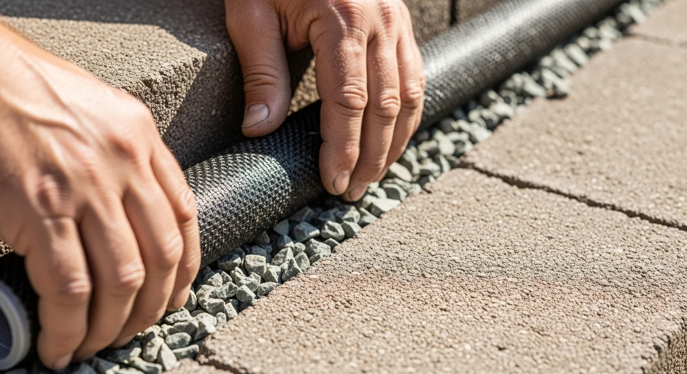
Mistake: Not Placing Filter Fabric Between the Drainage Gravel and the Native Soil
Without a non‑woven geotextile separator, fines from the backfill will migrate into the drainage column and clog it. Within a few seasons, the drain stops working and hydrostatic pressure returns. The fix: wrap the drainage gravel and perforated pipe in a continuous layer of filter fabric. Our landscape fabric overlap calculator can help you estimate material requirements and correct overlap.
Mistake: Using a Zero Setback Angle for a Block Wall That Actually Has Built‑In Lean
Many segmental blocks have a 5‑7° setback per course. Entering 0° removes the stability bonus and may push the wall into a higher risk band unnecessarily. The fix: check the block manufacturer’s data sheet; if unknown, use 6°.
Mistake: Assuming Drainage Base Depth Is Just Gravel Under the First Block
The calculated drainage base depth is the compacted aggregate foundation beneath the wall, not the gravel drainage column behind it. People sometimes treat them as the same thing and skimp on one or the other. The fix: prepare a separate, level, and compacted base layer of clean stone to the depth shown, independent of the backfill drainage.
Next Steps in Your Workflow
Once the calculator shows your total overturning force and the drainage dimensions, the next move is to gather materials that match those numbers exactly. Order the geogrid in rolls that cover the required embedment length plus a return at the face; the 0.60 × H figure is the minimum embedment, so add extra for wrapping and connection. For the drainage base, buy clean, angular ¾‑inch crushed stone and compact it in lifts before setting the first course. If the wall will support a patio above, check out our paver base calculator to size the base for both the wall and the paved area simultaneously.
If your wall exceeds 6 ft or the risk gauge lands in the red, stop and get a soils report. The tool intentionally over‑warns when water is involved because that’s the failure nobody sees coming. Even if local code doesn’t require a permit, a licensed engineer can verify the geogrid layout and drainage details. And if you’re placing large accent boulders near the wall for landscaping, a quick boulder weight check will keep you from adding an unintended surcharge.
FAQ
Why does the calculator show “Total Force (no drainage)” as the main result instead of the safe, drained number?
The undrained number represents the worst‑case scenario when water is trapped behind the wall. This is the failure condition that catches people off guard. By making it the primary output, the tool forces you to confront what happens if the drain clogs or isn’t built. The drained force is still available in the breakdown cards.
Can I use this calculator for a dry‑stacked stone wall without mortar?
Yes, but apply the same standards. Dry‑stacked walls rely on gravity and setback even more. The geogrid and drainage recommendations remain the same. The risk gauge will still flag height and soil issues; a dry‑stacked wall over 4 ft with clay soil is particularly vulnerable to hydrostatic blowout.
What if my wall has varying heights along its length?
Run the calculator at the tallest section. Overturning force increases with the square of height, so the highest point governs the worst‑case loading. To be safe, design the entire wall for that maximum height and extend the drainage detail consistently.
How accurate is the setback reduction factor?
The reduction is an approximation based on shifting the center of gravity inward. It’s conservative for typical segmental walls with horizontal backfill. For very steep battered walls or walls with a sloped backfill, a full stability analysis is needed. Treat the factor as a small bonus, not a substitute for proper sizing.
Does the calculator assume any embedment depth below grade?
The height you enter is the exposed face only. Embedment adds stability against sliding but is not included in the force calculation. As a rule of thumb, embedment should be about 10% of the exposed height plus 6 inches, but that’s separate from this tool’s scope.
Is the “Min Geogrid Length” the same as the reinforcement length for all grid layers?
The number shown is the shortest length for the lowest geogrid layer. Upper layers may be shorter, but all grids should connect to the facing unit. The 0.60 × H rule is a common starting point; manufacturer‑specific guidelines or an engineer’s design may modify this length.
Conclusion
A retaining wall’s true enemy is water, not soil. By putting hydrostatic pressure front and center and giving you a drainage plan in inches, this calculator avoids the polite fiction that soil alone causes failure. The risk gauge and warnings connect the numbers to real construction thresholds so you don’t have to guess when a professional’s stamp becomes mandatory.
If you take one thing away, let it be this: never build a wall taller than your knee without a gravel drainage column and a way for water to get out. The most beautifully stacked wall will lean or fall if water pressure is allowed to build. Use the tool, size the drainage base correctly, and install the geogrid to the depth it demands.
Lead Data Architect
Umer Hayiat
Founder & Lead Data Architect at TheYieldGrid. I bridge the gap between complex agronomic data and practical growing, transforming verified agricultural science into accessible, mathematically precise tools and guides for serious growers.
View all tools & guides by Umer Hayiat →