Lateral earth pressure in a segmental retaining wall does not distribute evenly from top to bottom. The maximum outward force concentrates in the bottom third of the wall, a zone engineers call the hinge point. That is where the wall is most likely to bulge, rotate at the base, or catastrophically blow out. Yet the single most common DIY reinforcement pattern places geogrid only at the top course, leaving the highest-pressure zone completely unreinforced. This calculator is built specifically to expose and fix that failure mode.
This tool calculates minimum geogrid length, vertical spacing intervals, total layer count, and a course-by-course layer schedule for segmental block retaining walls up to 12 feet tall. It adjusts for soil friction angle, active earth pressure coefficient, and surcharge conditions. What it does not do: replace a licensed geotechnical engineer’s analysis for walls subject to unusual drainage, seismic loading, hydrostatic pressure, or non-standard block geometry. If you are also estimating overall wall dimensions and block quantities, the retaining wall calculator handles that companion calculation.
After running this tool, you will know exactly which courses require geogrid, how far back each layer must extend into the hillside, and whether your wall height and soil combination trigger a structural engineering requirement before the first block is set.
Use the Tool
Retaining Wall Geogrid Calculator
Spacing, length & tensile strength — The Yield Grid
Geogrid Layer Schedule
Quick Reference: Wall Height vs. Grid Length
| Wall Height (ft) | Min Grid Length (ft) | Layers | Spacing |
|---|
How This Calculator Works
Step 1 — Minimum Grid Length:
Grid Length = max(4 ft, Wall Height × 0.60)
The reinforcement zone must extend at least 60% of the wall height behind the face, with a 4-foot absolute minimum per NCMA/FHWA guidelines.
Step 2 — Surcharge Adjustment:
If surcharge present: Grid Length = Wall Height × 0.75
Parking loads or slopes above the wall increase lateral earth pressure, requiring longer grids.
Step 3 — Vertical Spacing:
Max spacing = 24 inches (every 3rd standard course)
If Clay soil: spacing reduced to 16 inches
Clay soils exert higher lateral pressure and have poor internal friction, requiring tighter grid spacing.
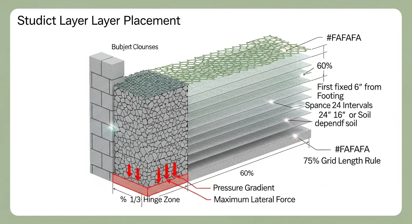
Step 4 — Layer Placement:
Layers are placed starting from the base, spaced upward at the calculated interval. The first layer is always at or near the base (within 6 inches of footing).
Step 5 — Risk Assessment:
Walls over 4 ft with clay soil and surcharge loads receive the highest risk rating. The “hinge point” (bottom 1/3 of wall) is where maximum outward pressure occurs and must always have grid reinforcement.
Assumptions & Limits
- Assumes gravity-type segmental retaining wall (SRW) with granular backfill in the reinforced zone.
- Wall heights above 4 ft are considered structural; local permits and engineered plans may be required.
- Geogrid tensile strength assumed at standard biaxial (BX) grade: 600–1,200 lb/ft ultimate for residential.
- Soil friction angles used: Clean Sand 34°, Silty Sand 30°, Silty Clay 26°, Clay 22°.
- This tool is for planning and education. Always consult a licensed geotechnical engineer for walls >4 ft or with surcharge loads.
- Block height assumed at 8 inches (standard). Adjust course count if using non-standard blocks.
- Does not account for seismic loading, hydrostatic pressure, or unusual site conditions.
Before entering inputs, have three measurements ready: the total finished wall height in feet, the planned block depth front-to-back in inches, and a soil classification for the material you will use as backfill behind the reinforced zone. Surcharge type requires a site observation, not a measurement. If a driveway, parking area, or uphill slope sits within a horizontal distance equal to the wall height from the top of the wall, select the applicable surcharge. Results update only after all four fields are filled and the calculate button is pressed.
Quick Start (60 Seconds)
- Wall Height: Measure finished height from the base footing course to the top of the last block, in feet. Do not include buried footing depth. Entry range is 1 to 12 feet; anything above 4 feet is flagged as structurally significant in the output.
- Soil Type: Select the material that will fill the reinforced zone directly behind the wall face. If you plan to import granular fill, choose Clean Sand or Gravel regardless of native site soil. Clay and Silty Clay selections reduce vertical spacing to 16 or 20 inches because cohesive soils carry a higher active pressure coefficient.
- Surcharge Load: Choose None only if the grade above the wall is flat and no vehicle or structure load sits within a horizontal distance equal to the wall height. A gravel driveway qualifies as Parking Lot surcharge; a sloped yard qualifies as Slope Above Wall. When in doubt, select the more conservative option.
- Block Depth: Enter the front-to-back dimension of the block unit in inches, typically 10 to 14 inches for standard SRW block. Do not confuse this with block face height (usually 8 inches) or block width.
- Units matter: Wall height must be in feet (decimals accepted); block depth must be in inches. Mixing units is the most common data-entry error.
- Read the layer schedule first: The primary output number (minimum grid length) matters less than the layer schedule table below it. That table tells you exactly which course to place grid on, starting from the base.
Inputs and Outputs (What Each Field Means)
| Field | Unit | What It Represents | Common Entry Mistake | Safe Guidance |
|---|---|---|---|---|
| Wall Height | Feet | Total exposed height of the wall from base course to top | Including buried footing depth, which inflates the result | Measure exposed face height only; 1 to 12 ft accepted |
| Soil Type | Category | Backfill friction angle and active pressure coefficient (Ka) | Selecting site soil instead of planned import fill material | Use the material you will actually place; clean granular fill is always preferred for the reinforced zone. See also the gravel calculator for fill volume estimates. |
| Surcharge Load | Category | Additional vertical load above the reinforced zone that increases lateral earth pressure | Selecting None when a slope or driveway exists within one wall-height of the crest | When in doubt, choose the more severe option; the grid length increase is small and the safety margin is large |
| Block Depth | Inches | Front-to-back dimension of the block unit; used to verify grid extension clears the block body | Entering block face height (8 in) instead of block depth (typically 10 to 14 in) | Check block manufacturer spec sheet; 6 to 24 in accepted |
| Min Grid Length (output) | Feet | Minimum horizontal distance geogrid must extend behind the back face of the block | Treating this as the distance from the front face of the block, not the back face | Always measure from the back of the block, not the wall face |
| Layer Schedule (output) | Inches from base | Exact vertical positions where geogrid must be placed, starting from the base course | Counting courses from the top instead of from the footing | First layer is always within 6 inches of the footing; count up from there |
| Risk Level (output) | Low / Moderate / High | Composite score combining wall height, soil type, surcharge, and hinge zone coverage | Assuming Low risk means no engineering review needed for taller walls | Any wall above 4 ft with surcharge or clay soil warrants a licensed engineer review regardless of risk score |
Worked Examples (Real Numbers)
Example 1: Residential Garden Tier, 4-Foot Clean Sand Wall
- Wall Height: 4 ft
- Soil Type: Clean Sand (friction angle 34 degrees, Ka = 0.283)
- Surcharge: None
- Block Depth: 12 inches
Result: Minimum grid length = max(4 ft, 4 × 0.60) = 4.0 ft. Vertical spacing = 24 inches. Two geogrid layers: one at 6 inches from footing, one at 30 inches from footing. Hinge zone (0 to 16 inches) has 1 layer. Risk level: Low.
A 4-foot clean sand wall with no surcharge is the simplest structural case. Two layers placed from the base are sufficient, but skipping the first layer near the footing, even at this modest height, eliminates the only reinforcement in the hinge zone entirely.
Example 2: Driveway Retention, 6-Foot Silty Clay with Parking Surcharge
- Wall Height: 6 ft
- Soil Type: Silty Clay (friction angle 26 degrees, Ka = 0.395)
- Surcharge: Parking Lot
- Block Depth: 12 inches
Result: Minimum grid length = max(4 ft, 6 × 0.75) = 4.5 ft. Vertical spacing tightened to 20 inches due to cohesive soil. Four geogrid layers at: 6 in, 26 in, 46 in, and 66 in from the footing. Hinge zone (0 to 24 inches) has 1 layer. Risk level: High.
The combination of parking surcharge and silty clay pushes the active earth pressure coefficient to 0.395, nearly 40 percent higher than clean sand. Grid length increases by 0.9 feet over the base case, and spacing drops from 24 to 20 inches. This wall requires a permit in most jurisdictions and likely an engineer’s review.
Example 3: Slope Retention, 8-Foot Silty Sand with Uphill Grade
- Wall Height: 8 ft
- Soil Type: Silty Sand (friction angle 30 degrees, Ka = 0.333)
- Surcharge: Slope Above Wall
- Block Depth: 12 inches
Result: Minimum grid length = max(4 ft, 8 × 0.75) = 6.0 ft. Vertical spacing = 24 inches. Four geogrid layers at: 6 in, 30 in, 54 in, and 78 in from the footing. Hinge zone (0 to 32 inches) has 2 layers. Risk level: High.
An 8-foot wall with a slope above it is a structural project without exception. Grid length jumps to 6.0 feet, requiring excavation 6 feet behind the wall face plus the block depth. The two hinge-zone layers represent the minimum safe coverage for this condition; more layers are not harmful and are sometimes specified by engineers on sloped sites.
Reference Table (Fast Lookup)
| Wall Height | Soil Type | Surcharge | Min Grid Length | V-Spacing | Total Layers | Hinge Zone Layers |
|---|---|---|---|---|---|---|
| 4 ft | Clean Sand | None | 4.0 ft | 24 in | 2 | 1 |
| 4 ft | Clay | None | 4.0 ft | 16 in | 3 | 1 |
| 5 ft | Silty Sand | None | 4.0 ft | 24 in | 3 | 1 |
| 6 ft | Clean Sand | None | 4.0 ft | 24 in | 3 | 1 |
| 6 ft | Silty Clay | Parking Lot | 4.5 ft | 20 in | 4 | 1 |
| 6 ft | Clay | Slope Above | 4.5 ft | 16 in | 5 | 2 |
| 8 ft | Silty Sand | None | 4.8 ft | 24 in | 4 | 2 |
| 8 ft | Clay | Parking Lot | 6.0 ft | 16 in | 6 | 2 |
| 10 ft | Silty Sand | Slope Above | 7.5 ft | 24 in | 5 | 2 |
| 12 ft | Clay | None | 7.2 ft | 16 in | 9 | 3 |
The “Hinge Zone Layers” column is the derived safety check column. Any row showing 0 in that column represents a catastrophic failure condition. The table confirms that even the simplest 4-foot clean sand wall requires at least 1 layer in the hinge zone.
How the Calculation Works (Formula + Assumptions)

Show the calculation steps
Step 1: Minimum Grid Length
The base formula derives from NCMA and FHWA mechanically stabilized earth (MSE) guidelines for segmental retaining walls:
Grid Length = max(4 ft, Wall Height × 0.60)
The 4-foot absolute floor exists because grids shorter than 4 feet do not engage sufficient friction area to resist sliding or overturning at any practical wall height. The 0.60 multiplier represents the minimum reinforcement zone depth-to-height ratio for granular soils without surcharge.
Step 2: Surcharge Adjustment
When surcharge is present (parking or slope), the multiplier increases from 0.60 to 0.75:
Grid Length = max(4 ft, Wall Height × 0.75)
The longer grid extends the passive resistance zone to counteract the increased driving force from the additional surface load.
Step 3: Soil-Dependent Vertical Spacing
Vertical spacing between geogrid layers is set by soil friction angle:
Clean Sand (phi = 34 deg): 24 inches
Silty Sand (phi = 30 deg): 24 inches
Silty Clay (phi = 26 deg): 20 inches
Clay (phi = 22 deg): 16 inches
Lower friction angle soils generate higher active earth pressure (Ka), requiring tighter vertical spacing to limit the horizontal tensile force accumulated in each geogrid layer.
Step 4: Layer Placement Schedule
The first layer position is fixed at 6 inches above the footing. Subsequent layers are placed at each spacing interval above that. The algorithm iterates upward while the layer position remains at or below total wall height in inches. The result is a precise course-by-course schedule, not a rounded approximation.
Step 5: Hinge Zone Assessment
The hinge zone is defined as the bottom one-third of the wall (Wall Height / 3). The calculator counts how many scheduled layers fall within this zone. Zero layers in the hinge zone triggers a critical failure warning. The risk score is composite: wall height above 4 feet, soil friction angle, surcharge severity, and hinge zone coverage each contribute a weighted component.
Rounding rules: Grid length is displayed to one decimal place. Layer positions are whole numbers in inches derived from the iterative schedule. Hinge zone boundary is rounded to the nearest inch.
Assumptions and Limits
- Block face height is assumed to be 8 inches (standard SRW unit). Walls using non-standard block heights will have slightly different course-to-layer alignments; adjust course numbers accordingly.
- Soil friction angles are mid-range values for each classification (Clean Sand: 34 deg, Silty Sand: 30 deg, Silty Clay: 26 deg, Clay: 22 deg). Actual field values can vary by 2 to 5 degrees; a geotechnical lab test provides accurate site-specific data.
- The Ka values used are for a level backfill condition in the base formula. Surcharge selection adds a simplified conservative adjustment, not a full Rankine or Coulomb calculation with a sloped backfill surface.
- This tool assumes compacted granular fill within the reinforced zone even when clay is selected. If native clay is left unexcavated in the reinforced zone, the actual pressures are higher than the calculator shows.
- Hydrostatic pressure from groundwater is not modeled. Walls in areas with seasonal high water tables require drainage design beyond this tool’s scope.
- Seismic loading is not included. In seismic design categories C and above, grid lengths and layer counts must be increased per FHWA or local code requirements.
- The 12-foot height ceiling reflects the practical limit for residential SRW without specialty block systems or tiered construction. Walls above 12 feet typically use mechanically stabilized earth (MSE) engineering with project-specific grid specifications.
- Grid tensile strength selection (Tensar BX1200 or equivalent biaxial grid rated at 600 to 1,200 lb/ft) is assumed as adequate for residential conditions. Walls adjacent to structures or retaining surcharge above 250 lb/sq ft may require uniaxial grid with higher tensile ratings.
Standards, Safety Checks, and “Secret Sauce” Warnings
Critical Warnings
- The hinge point failure: The bottom third of every retaining wall carries the highest outward earth pressure. Placing geogrid only at the top of the wall, or skipping the first two or three base courses entirely, leaves this zone with zero tensile reinforcement. The base can rotate outward while the top remains plumb, creating a sudden bulge and eventual blowout. The calculator flags any scenario where the hinge zone has no scheduled grid layers.
- Clay backfill spacing violations: Using 24-inch vertical spacing with clay or silty clay backfill is a common field deviation. Clay has an active earth pressure coefficient roughly 60 percent higher than clean sand, meaning the tensile load in each grid layer is proportionally higher. The NCMA Design Manual for Segmental Retaining Walls requires tighter spacing for cohesive soils precisely because of this load concentration. This tool enforces 16-inch spacing for clay and 20-inch for silty clay.
- Surcharge creep: A gravel driveway installed after wall completion, or a slope regraded years later, can convert a no-surcharge wall into a surcharge-loaded wall retroactively. Original geogrid layouts built without surcharge consideration may be undersized for the new condition.
- Permit thresholds: Most jurisdictions classify retaining walls above 4 feet as structural elements requiring a building permit and, in many cases, a licensed engineer’s sealed drawings. Check local code before breaking ground. The paver base calculator covers base compaction depth requirements for adjacent hardscape that often accompanies wall construction.
Minimum Standards
- Grid length must be at least 4 feet or 0.60 times wall height (whichever is greater) for walls without surcharge, per NCMA guidelines.
- Grid length must be at least 0.75 times wall height for walls with parking or slope surcharge.
- At least one geogrid layer must fall within the bottom third of the wall in every configuration without exception.
- Backfill over geogrid must be compacted in 6- to 8-inch lifts using vibratory plate equipment; heavy compaction directly on the grid layer can displace it before the next course is set.
Competitor Trap: A large number of retaining wall guides, online articles, and even some contractor handouts describe geogrid as something you add at the top of a wall to “tie it back.” This framing is structurally incorrect and has contributed to real-world wall failures. Geogrid works by engaging frictional resistance between the grid and the backfill, creating a coherent reinforced mass behind the wall face. That reinforced mass must exist where the earth pressure is highest, which is at the base. Articles that show a single grid layer at the third or fourth course from the top, with nothing near the footing, are describing an underbuilt wall. This calculator enforces base-first placement as non-negotiable. For slope-related drainage considerations that affect wall longevity, the gravel driveway slope calculator addresses runoff management adjacent to retaining structures.
Common Mistakes and Fixes
Mistake: Placing the First Geogrid Layer at Mid-Wall
Many DIY guides reference “every three courses” as the geogrid rule, leading builders to start counting from the first visible course above grade rather than from the footing. If the wall has a buried first course, the first grid layer ends up at the 4th or 5th course from the actual base. This leaves the hinge zone completely unprotected. The fix: always place the first geogrid layer at the first or second course above the footing, regardless of what is visible from the finished grade.
Mistake: Using Native Clay as Reinforced Zone Backfill
Excavating a hillside exposes native clay, and it is tempting to push that material back behind the wall rather than hauling in clean fill. Clay in the reinforced zone has three compounding problems: it drains poorly (generating hydrostatic pressure), it has a high active earth pressure coefficient (increasing lateral load), and it loses strength when saturated. The calculator’s clay spacing settings assume you are still using properly drained backfill in the reinforced zone. If native clay is left in place, actual pressures are higher than shown. Fix: import a minimum 12-inch-wide column of clean crushed stone or gravel behind the wall face within the reinforced zone, with a perforated drain pipe at the base.
Mistake: Measuring Grid Length from the Wall Face Instead of the Back of the Block
A common field measurement error adds block depth to the total excavation requirement. If the block is 12 inches deep and the minimum grid length is 4.0 feet, the grid must extend 4.0 feet behind the back face of the block, meaning the total excavation from the wall face is 4.0 feet plus 1.0 foot of block depth, totaling 5.0 feet. Builders who excavate exactly 4.0 feet from the wall face are short by the full block depth. Fix: add block depth to the minimum grid length to calculate total excavation width.
Mistake: Skipping Geogrid on Shorter Courses at the Top
When a wall steps down at a corner or transitions to a shorter section, builders sometimes omit geogrid from the shorter segment, reasoning that a 2-foot section “doesn’t need it.” Any section of wall above 18 inches that connects to a reinforced section needs geogrid continuity; an unreinforced segment acts as a weak point that transfers shear load to adjacent sections. If you are planning adjacent outdoor stair construction alongside a retaining wall, the outdoor stair riser calculator accounts for grade transitions that often intersect with wall termination points.
Mistake: Ignoring the 4-Foot Absolute Grid Length Minimum
For a 3-foot-tall wall, the formula gives 3 × 0.60 = 1.8 feet. Some builders interpret this as the actual required grid length and cut grids at 2 feet. The 4-foot absolute minimum exists for a specific structural reason: grids shorter than 4 feet do not develop adequate interface friction to resist sliding, regardless of wall height. The frictional capacity scales with grid contact area, and below 4 feet that area becomes insufficient for standard soil densities. Fix: never cut grid shorter than 4 feet, even for low walls.
Next Steps in Your Workflow
Once you have the layer schedule and minimum grid length from the calculator, the next step is confirming your excavation plan. Total excavation width from the wall face equals minimum grid length plus block depth. Excavation depth for the footing trench is typically 6 to 12 inches below finished grade for the base course plus a 6-inch compacted gravel pad. If you are calculating how much topsoil to remove or backfill to the finished grade after wall construction, the topsoil calculator handles cut-and-fill volume for the surrounding landscape area.
For long walls or walls with drainage fabric requirements behind the block face, estimating landscape fabric coverage is a separate calculation. The overlap and coverage math for geotextile separation fabric behind retaining walls follows a specific methodology covered by the landscape fabric overlap calculator. The fabric layer is not a replacement for proper backfill drainage, but it prevents fine soil particles from migrating into the granular drainage column over time, which would reduce drainage capacity and increase hydrostatic pressure against the wall face.
FAQ
How many layers of geogrid does a 6-foot retaining wall need?
For a 6-foot wall with clean sand backfill and no surcharge, the calculator schedules 3 geogrid layers: at 6 inches, 30 inches, and 54 inches from the footing. Clay backfill with a slope surcharge at the same height requires 5 layers due to tighter 16-inch spacing. The specific number depends entirely on soil type and surcharge conditions, not wall height alone.
What is the minimum geogrid length for a retaining wall?
The absolute minimum is 4 feet, regardless of wall height. For walls taller than approximately 6.7 feet, the formula (0.60 × height) produces a result larger than 4 feet and becomes the controlling dimension. Surcharge conditions increase the multiplier to 0.75, yielding longer required grid for the same wall height. Grid length is always measured from the back face of the block, not the front face.
What is the “hinge point” in a retaining wall?
The hinge point refers to the zone in the bottom third of a retaining wall where lateral earth pressure peaks. As retained soil pushes against the wall, the wall tends to rotate outward from a pivot point near its base. If the base is not anchored by geogrid reinforcement engaging the backfill, the lower section can translate or rotate while the top stays in place, producing a visible bulge and eventual structural failure.
Can I use clay as backfill behind a geogrid retaining wall?
Clay is a poor choice for reinforced zone backfill because of its high active earth pressure coefficient, low drainage capacity, and tendency to lose strength when saturated. If clay must be used, geogrid spacing must be reduced to 16 inches, a robust perforated drainage system is required at the wall base, and a licensed engineer should review the design. The calculator flags clay selections with a specific warning about cohesive soil conditions.
Does a retaining wall under 4 feet need geogrid?
Walls under 4 feet do not always require geogrid reinforcement depending on soil conditions, but the calculator recommends at least one base layer for any wall in clay soil or with surcharge, even at modest heights. Without geogrid, a short wall relies entirely on block setback (batter) and deadman courses for stability, which is adequate for some clean sand conditions but not for cohesive soils or loaded sites.
How deep should geogrid extend behind a retaining wall?
Grid extension depth is the minimum grid length output from the calculator, measured from the back face of the block. For a no-surcharge wall, this is the greater of 4 feet or 60 percent of the wall height. With a parking or slope surcharge, it increases to 75 percent of the wall height. This dimension sets the required excavation width beyond the block body for proper grid placement.
Conclusion
The core engineering principle this calculator enforces is simple: geogrid reinforcement must start at the base of a retaining wall, not somewhere in the middle or at the top. The hinge point failure mode has a well-documented root cause that is easy to prevent when the layer schedule is planned correctly before the first block is set. Soil type and surcharge conditions drive spacing and length requirements in ways that a single rule-of-thumb cannot capture accurately, which is why the calculator uses soil friction angles and active pressure coefficients rather than a generic “every three courses” shortcut.
After running the calculation, compare the required excavation width against your available site clearance before committing to a wall height. Many projects discover that a specified grid length requires excavating into an existing slope, structure, or utility corridor. Adjusting wall height or selecting terraced wall tiers is often simpler than excavating through constraints. For walls that adjoin footings, fence posts, or other buried structures, the fence post depth calculator helps coordinate embedment depths to avoid conflicts with the geogrid reinforcement zone below.
Lead Data Architect
Umer Hayiat
Founder & Lead Data Architect at TheYieldGrid. I bridge the gap between complex agronomic data and practical growing, transforming verified agricultural science into accessible, mathematically precise tools and guides for serious growers.
View all tools & guides by Umer Hayiat →