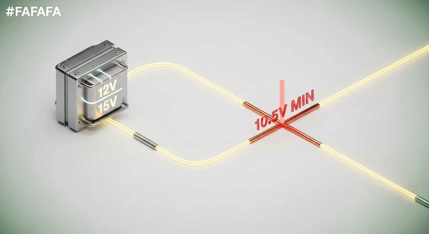
Most landscape lighting failures don’t come from bad lamps or cheap transformers. They come from a miscalculation that starves the last fixture of voltage. When a low-voltage system drops below 10.5 V at any point, LED drivers can’t regulate properly. Color shifts toward orange, output sags, and one fixture after another goes dim while the first one blazes. That’s not a manufacturing flaw—it’s a wiring design problem that a disciplined voltage drop check eliminates before the first trench is dug.
This tool calculates the exact delivered voltage at the farthest fixture on your wire run, using the real NEC-aligned resistance values for solid copper, your transformer’s tap setting, and the actual topology you plan to wire. It doesn’t just spit out a single number. It flags when the daisy-chain dim-out effect is quietly undermining the installation, shows you exactly how much voltage you’d save by switching to hub/T‑tap wiring, and builds a comparative reference table across all four common wire gauges so you can make a fast material decision. It does not estimate brightness in lumens, predict fixture lifespan, or account for high‑impedance splices—it’s a pure voltage‑drop engine built for low‑voltage landscape circuits.
After using the calculator, you’ll know whether your current tap and wire gauge keep every fixture above the 10.5 V threshold, which AWG alternative solves the problem at the lowest cost, and exactly when to abandon a daisy chain in favor of a hub layout. If you’re also building hardscape elements, the retaining wall calculator helps you plan the structural side so your lighting conduit ends up in the right place.
Use the Tool
Landscape Lighting Voltage Drop & Tap Selector
Calculate delivered voltage, detect dim-out zones, and find the right transformer tap
—
—
Warnings & Standards
- Run the calculation to see diagnostic checks.
Wire Gauge Drop Reference — Your Load & Distance
| AWG | Ω/1000 ft | V Drop | Delivered V | Status |
|---|---|---|---|---|
| Run calculation to populate table | ||||
How This Calculator Works — Formula & Assumptions
This landscape lighting voltage drop calculator uses the standard low-voltage (12V/15V) wire-resistance formula recommended by the NEC and major manufacturers (Volt Lighting, Kichler, CAST Lighting).
Step-by-step Formula
Why 2× distance? Current must travel from the transformer to the last fixture and back through the return conductor — the full round-trip length.
Daisy Chain vs Hub/T-Tap: In a daisy chain the full load current flows through the entire wire run. With hub/T-tap wiring, each home-run wire carries only a fraction of the total load, dramatically reducing drop and equalizing brightness across all fixtures.
Wire resistance values used (solid copper at 20°C): 16 AWG = 1.340 Ω/1000 ft, 14 AWG = 0.843 Ω/1000 ft, 12 AWG = 0.530 Ω/1000 ft, 10 AWG = 0.333 Ω/1000 ft.
Assumptions & Limits: Assumes solid copper wire, 20°C ambient, resistive (non-inductive) loads, and all fixtures at the same end of the run (worst-case for daisy chain). Voltage drop increases with temperature and with aluminum wire. Not valid for 120V systems or AC circuits.
Compliance: NEC Article 411 governs low-voltage landscape lighting. Maximum 12V system voltage at any fixture for class 2 wiring.
Recommended Products for This Run
Transformers
- Volt® 300W Multi-Tap Stainless Steel Transformer (12/13/14/15V taps) — best for long runs
- Kichler® 300W Low Voltage Transformer with Photo Sensor
Wire
- 12/2 Direct Burial Copper Wire Spool (250 ft) — recommended gauge for most installs
- 10/2 Direct Burial Copper Wire Spool — for runs over 150 ft with heavy loads
Connectors & Fixtures
- Silicone-Filled Waterproof Wire Nuts (DBR series) — prevent corrosion at splices
- Cast-Brass LED Path Lights (5W, 3000K) — consistent output, long lifespan
- Hub / T-Tap Quick Connectors — pierce-and-seal for hub wiring
Before you run the calculation, have these numbers ready: the one‑way distance in feet from transformer to the last fixture, the total wattage of all fixtures on that run (add them up), the wire gauge you intend to use, and the transformer tap voltage you’ve selected. If you haven’t yet chosen a gauge, start with 12 AWG direct‑burial copper as the industry baseline and let the tool show you whether it’s safe or needs an upgrade. For the most accurate result, measure the actual run length along the trench path, not the straight‑line distance.
Quick Start (60 Seconds)
- Enter Total Distance to Last Fixture in feet—this is the one‑way wire length, not round‑trip. The tool automatically doubles it for the return path.
- Pick Wire Gauge (AWG) from the dropdown. If you’re unsure, start with 12 AWG; the reference table will show you every gauge’s performance side‑by‑side.
- Sum all fixture wattages on the circuit and put the number in Total Wattage on Run. LED path lights often draw 3–5 W each; halogens may pull 20 W or more.
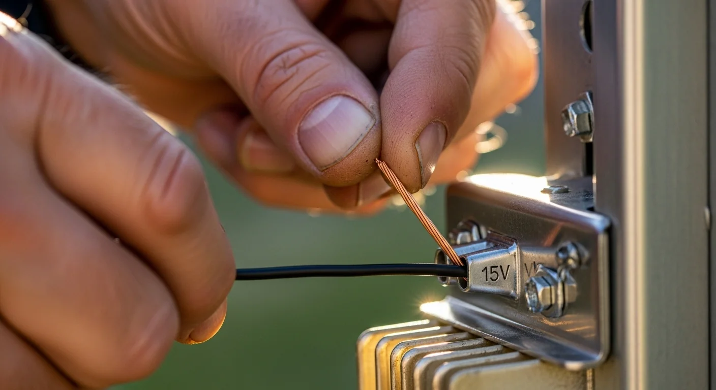
- Choose the Transformer Tap Voltage you’ve set or plan to set. Multi‑tap transformers typically offer 12, 13, 14, and 15 V taps.
- Select Wiring Topology: Daisy Chain if the wire passes from fixture to fixture; Hub/T‑Tap if each fixture gets its own home‑run wire from a central junction.
- Press Calculate Voltage Drop. The gauge bar, the warnings list, and the comparison table all update instantly.
- If the delivered voltage is below 10.5 V, the tool will recommend a specific tap increase or wire gauge change. Act on that before you buy materials.
If you’re still in the planning phase and need to figure out the turf area that the lighting will illuminate, the grass seed calculator can help you estimate the square footage while you mark out fixture locations.
Inputs and Outputs (What Each Field Means)
| Input / Output | Unit | What It Means | Common Mistake | Safe Entry Guidance |
|---|---|---|---|---|
| Total Distance to Last Fixture | feet | One‑way wire length from transformer to the final fixture on the run. | Entering the round‑trip distance instead of one‑way; the tool doubles it internally. | Measure along the actual trench route, not as the crow flies. Stay within 1–2000 ft. |
| Wire Gauge (AWG) | AWG | American Wire Gauge of the copper conductor. Lower numbers mean thicker wire and less resistance. | Choosing 16 AWG for any run over 50 ft; that gauge quickly leads to >12% drop. | Use 12 AWG as default; go to 10 AWG for heavy loads beyond 150 ft. |
| Total Wattage on Run | Watts | Sum of the rated wattage of every fixture on this single circuit. | Forgetting to include all fixtures, especially accent lights added later. | Double‑check the transformer label and add a 10% buffer for future expansion. |
| Transformer Tap Voltage | Volts | The output voltage setting on the transformer’s multi‑tap terminal. | Assuming 12 V tap is always sufficient, even on long runs. | Start with the 12 V tap, then use the tool to see if a higher tap is needed. |
| Wiring Topology | — | Daisy Chain: wire runs through each fixture in series. Hub/T‑Tap: dedicated home‑run to each fixture. | Using daisy chain for long runs and expecting equal brightness at every fixture. | For runs over 80 ft with more than 60 W, strongly prefer hub wiring. |
| Delivered Voltage (output) | Volts | Calculated voltage at the last fixture, accounting for total wire resistance. | Ignoring values below 10.5 V and blaming the lamp instead of the wiring. | If below 10.8 V, review the warnings; below 10.5 V, immediate correction needed. |
| Voltage Drop (output) | Volts | Total volts lost in the wire due to resistance over the full round‑trip. | Assuming a drop of 1 V is always acceptable without checking the threshold. | A drop exceeding 1.5 V on a 12 V system typically pushes you into the marginal zone. |
| Drop % (output) | % | Voltage drop expressed as a percentage of the tap voltage. | Believing that 10% drop is safe for LEDs; the 10.5 V floor is the real limit. | Any value above 12.5% on a 12 V tap means you’ve fallen under 10.5 V delivery. |
When your trench path must navigate around established trees, consult the tree root protection calculator to avoid cutting critical roots while still keeping the wire run to a minimum length.
Worked Examples (Real Numbers)
Standard Backyard Path Lights, 12 AWG, Daisy Chain
- Distance: 100 ft
- Wire Gauge: 12 AWG
- Total Wattage: 60 W
- Tap Voltage: 12 V
- Topology: Daisy Chain
Result: Delivered voltage = 11.47 V, Voltage drop = 0.53 V, Drop = 4.4%, Status: Optimal.
A short run with moderate load on 12 AWG wire stays comfortably above the 10.8 V optimal zone. The reference table confirms that even 14 AWG would work here, but 12 AWG leaves headroom for adding a few more fixtures later.
Long Driveway Run, 14 AWG, Daisy Chain—Dim‑Out Risk
- Distance: 200 ft
- Wire Gauge: 14 AWG
- Total Wattage: 100 W
- Tap Voltage: 12 V
- Topology: Daisy Chain
Result: Delivered voltage = 9.19 V, Voltage drop = 2.81 V, Drop = 23.4%, Status: Insufficient.
This configuration falls far below the 10.5 V minimum. The tools warnings will flag a critical voltage failure, a daisy‑chain dim‑out alert, and will recommend moving to a 15 V tap or upgrading to 12 AWG wire. Without a change, the last fixtures will flicker or appear orange.
Same Driveway, 12 AWG and Hub/T‑Tap Fix
- Distance: 200 ft
- Wire Gauge: 12 AWG
- Total Wattage: 100 W
- Tap Voltage: 12 V
- Topology: Hub/T‑Tap
Result: Delivered voltage = 11.12 V, Voltage drop = 0.88 V, Drop = 7.4%, Status: Optimal.
Simply switching to hub wiring and a modestly thicker gauge eliminates the critical dropout. Each home‑run leg carries half the total load, so the voltage at every fixture is essentially equal. The gauge bar will show the improvement moving from the danger zone well into the safe green band.
Reference Table (Fast Lookup)
Calculations assume a 12 V transformer tap, solid copper conductors at 20°C, and the requirement to stay at or above 10.5 V at the last fixture. Hub/T‑Tap distances double because the effective current on each wire leg is halved.
| Total Load (W) | AWG | Max Distance Daisy Chain (ft) | Max Distance Hub/T‑Tap (ft) |
|---|---|---|---|
| 50 | 16 | 134 | 268 |
| 50 | 14 | 213 | 427 |
| 50 | 12 | 339 | 679 |
| 50 | 10 | 540 | 1080 |
| 100 | 16 | 67 | 134 |
| 100 | 14 | 106 | 213 |
| 100 | 12 | 169 | 339 |
| 100 | 10 | 270 | 540 |
| 150 | 16 | 44 | 89 |
| 150 | 14 | 71 | 142 |
| 150 | 12 | 113 | 226 |
| 150 | 10 | 180 | 360 |
| 200 | 16 | 33 | 67 |
| 200 | 14 | 53 | 106 |
| 200 | 12 | 84 | 169 |
| 200 | 10 | 135 | 270 |
For distances that fall between rows, always round down to the next shorter safe length or move up one wire gauge. The table assumes all fixtures sit at the very end of the run, which is the worst case for a daisy chain.
How the Calculation Works (Formula + Assumptions)
Show the calculation steps
The voltage drop follows the standard DC resistance formula for low‑voltage landscape lighting. The wire is treated as a purely resistive load—typical for LED and halogen fixtures at these voltages.
- Calculate current: Amps = Total Wattage ÷ Tap Voltage. For hub wiring, the effective wattage per leg is half the total because the load splits across two home‑run wires.
- Compute round‑trip resistance: The distance is multiplied by 2 to account for the current traveling to the fixture and back through the return conductor. The resistance per 1000 ft is taken from standard copper tables: 16 AWG = 1.340 Ω, 14 AWG = 0.843 Ω, 12 AWG = 0.530 Ω, 10 AWG = 0.333 Ω.
- Voltage drop: V_drop = (2 × Distance × Amps × Ω_per_1000ft) ÷ 1000.
- Delivered voltage: V_delivered = Tap Voltage − V_drop.
- Result interpretation: If V_delivered ≥ 10.8 V, the circuit is optimal. Between 10.5 V and 10.8 V, it’s marginal. Below 10.5 V, the tool issues a critical warning.
All results are rounded to two decimal places for voltage and current, and to one decimal for the drop percentage. The reference table distances are truncated to the nearest whole foot to ensure a conservative reading.
Assumptions & Limits
- Solid copper wire at 20 °C (68 °F). Higher temperatures increase resistance and will raise the actual voltage drop. In direct‑burial applications on hot days, the delivered voltage will be slightly lower than calculated.
- All fixtures are modeled at the far end of the wire run. In a real daisy chain with fixtures distributed along the run, the voltage at the last fixture will be slightly higher than the calculator’s worst‑case number. The tool intentionally shows the most conservative scenario.
- This calculator applies to low‑voltage (12–15 V) landscape lighting circuits only. It is not valid for 120 V line‑voltage systems, AC circuits, or aluminum wire.
- Fixture loads are treated as purely resistive, which is accurate for LED drivers and halogen lamps at these frequencies. If using magnetic transformers with long cable runs, reactive effects are negligible.
- The hub/T‑tap model assumes exactly two home‑run legs splitting the total load equally. If your hub serves more than two unequal legs, the result will still be far more balanced than daisy chain, but exact per‑fixture voltage may vary.
- The tool does not account for voltage drop across splices, connectors, or corroded terminals. Even a small additional resistance from a poorly sealed wire nut can drop another 0.3–0.5 V. Always use silicone‑filled connectors.
Standards, Safety Checks, and “Secret Sauce” Warnings
The widget runs several checks every time you press calculate. These aren’t generic suggestions—they’re deterministic flags that detect when a calculation result puts you into a known failure territory.
Critical Warnings
- Voltage floor violation: If the delivered voltage drops below 10.5 V, the system immediately flags a critical alert. LED drivers require a minimum input voltage to maintain constant current. Below this threshold, output collapses, color temperature warms, and flicker becomes unavoidable.
- Daisy‑chain dim‑out: When daisy chain topology is selected and the delivered voltage falls below 11.0 V, the tool warns that brightness will vary progressively from the first fixture to the last. This effect is impossible to tune out with tap changes alone—only a switch to hub wiring equalizes the voltage.
- Wire gauge mismatch: If 16 AWG is paired with a run over 100 ft, or 14 AWG over 150 ft, the tool highlights the excessive resistance and quantifies exactly how much voltage you’ll save by moving to 12 AWG.
- Over‑current alert: Loads that pull more than 15 A are flagged as exceeding typical residential transformer and wire ratings. Even at 12 V, 180 W pushes 15 A. Split the circuit or increase the system voltage.
Minimum Standards
- NEC Article 411 applies to low‑voltage landscape lighting systems operating at 30 V or less. The tool’s 10.5 V internal threshold aligns with the practical minimum for consistent LED performance, which is stricter than the NEC’s voltage‑drop recommendation but reflects real‑world LED behavior.
- Direct‑burial wire must be listed for underground use. The resistance values used in the calculator assume UL‑listed copper conductors. Aluminum wire, even if rated for direct burial, will show a markedly higher drop and is not covered by this tool.
- All wire connections must be made with moisture‑proof methods. Even a mathematically perfect voltage calculation is ruined by a corroded splice. Silicone‑filled wire nuts or gel‑filled connectors are a requirement, not an option.
Competitor Trap: Many online calculators ignore wiring topology entirely. They assume a single load at the end of a wire and output one number. In a daisy chain, that number is correct for the last fixture, but the calculator’s silence about the middle fixtures gives a false sense of uniform brightness. This tool explicitly separates daisy chain from hub/T‑tap and shows the dim‑out warning, which is the single largest differentiator between a professional‑grade install and a homeowner complaint call.
When you’re planning the irrigation zone that shares the same trench as your low‑voltage wire, the turf watering calculator helps ensure that the sprinkler layout doesn’t inadvertently conflict with your lighting conduit runs. Likewise, if tree roots force you to deviate from a straight path, the critical root zone calculator can keep your excavation within safe limits.
Common Mistakes and Fixes
Mistake: Using one‑way distance in a manual calculation
Voltage drop formulas require the total conductor length—current must travel out and back. Entering only the one‑way distance in some other calculators or doing the math by hand without doubling the length produces a drop that’s half of reality. Fix: Either use this tool, which automatically doubles the distance, or always multiply your one‑way measurement by 2 before plugging it into a manual formula.
Mistake: Choosing 16 AWG wire to save money on a 150 ft run
16 AWG has over four times the resistance of 10 AWG. On a 150 ft run with 80 W of load, a 12 V tap delivers less than 9 V to the last fixture. The $20 saved on wire evaporates the first time you have to dig up and replace it. Fix: Use the reference table in this page to see the maximum safe distance for each gauge before you buy a single spool.
Mistake: Assuming the 15 V tap will always fix a voltage drop problem
Bumping the tap from 12 V to 15 V adds 3 V to the delivered voltage, which often solves the problem. But if the run is extremely long and heavily loaded, even 15 V may not be enough, and the higher tap pushes more current, slightly increasing the drop in volts. Fix: Run the calculation at both 12 V and 15 V. If 15 V still leaves you under 10.5 V, you must upsize the wire or shorten the run—no tap can rescue you.
Mistake: Daisy chaining fixtures across a staircase without considering step‑to‑step voltage variation
On a staircase, the first fixture at the top may receive 12 V, while the bottom fixture receives 9.5 V. The brightness gradient becomes a safety hazard. Fix: Hub wiring with a central junction at the stair midpoint equalizes the voltage to every step. The outdoor stair riser calculator can help you plan the riser dimensions while you map the fixture placement.
Mistake: Adding fixtures to an existing run without recalculating
Even a few extra watts can push a previously safe circuit into the marginal or danger zone. The drop is directly proportional to current, so a 20% increase in load yields a 20% increase in voltage drop. Fix: Before adding any new fixture, re‑enter the new total wattage into the calculator and verify the delivered voltage remains above 10.5 V.
Next Steps in Your Workflow
After the calculator gives you a safe delivered voltage, lock in your wire gauge choice and order direct‑burial copper cable that is listed for underground use. If you settled on a hub/T‑tap topology, plan the location of your central junction box and measure the actual home‑run lengths to each fixture. Those individual wires each carry only their fixture’s load, so you can often drop down a gauge on the legs while keeping a heavier trunk feed from the transformer. Mark the junction point clearly on your site plan, because future troubleshooting depends on knowing where the split happens.
When you trench for the wire, keep it at least 6 inches away from irrigation lines and gas tracer wires, and use a continuous run without unnecessary splices. The landscape edging calculator can help you define the border of the planting bed where many path lights sit, so your conduit ends up exactly at the edge without guesswork. If you’re installing lights within a paved area, the paver base calculator ensures you have the correct compacted depth before you lay conduit under the base material.
FAQ
What is the minimum voltage for LED landscape lights?
Most LED landscape fixtures need at least 10.5 V at the fixture to operate correctly. Below that, the internal driver cannot maintain constant current, leading to dimming, flicker, and warmer color appearance. The calculator flags any result below 10.5 V as critical.
Does daisy chain or hub wiring give better voltage at all fixtures?
Hub wiring provides essentially equal voltage to every fixture because each home‑run wire carries only that fixture’s current. In a daisy chain, the full load current flows through the entire wire, causing a progressive voltage drop that increases with each successive fixture.
Can I use a 14 V or 15 V tap to fix a long run?
In many cases, yes. Raising the tap voltage from 12 V to 14 V or 15 V directly increases the delivered voltage by nearly the same amount, often bringing marginal runs back into the safe zone. However, if the drop is already severe, even a 15 V tap may not be enough, and a thicker wire gauge becomes necessary.
Why does the calculator double the distance I enter?
Electric current must travel from the transformer to the last fixture and then return through the neutral conductor. The total resistance path is twice the one‑way distance. The tool automatically applies this factor so you only need to input the one‑way measurement.
What wire gauge should I use for a 200‑foot run with 80 watts?
Based on the reference table and the calculator’s logic, 12 AWG in a hub configuration stays safe up to about 169 ft at 100 W on a 12 V tap, so 200 ft at 80 W with hub wiring often passes. In daisy chain, it may be marginal. Run the exact numbers through the tool with your actual tap setting to confirm.
Does the calculator account for splices and connectors?
No. The calculation assumes perfect connections. Real‑world splices, especially if not properly sealed, add small but cumulative resistance. For best results, keep splices to a minimum and use gel‑filled or silicone‑filled connectors, and consider adding a 0.3 V buffer to the calculated drop.
Conclusion
A landscape lighting voltage drop calculator that ignores wiring topology and only spits out a single undifferentiated number hides the real failure mode of most low‑voltage installs: daisy‑chain dim‑out. By explicitly modeling hub versus daisy chain, this tool turns a generic voltage drop check into a true design decision. The integrated warnings don’t just flag a low voltage—they name the specific fix, whether that’s a tap change, a wire gauge upgrade, or a topology switch, and they back each recommendation with computed voltage savings.
The number‑one mistake to avoid is treating the delivered voltage at the last fixture as the voltage everywhere. In a daisy chain, every fixture sees a different voltage, and the tool’s dim‑out alert is your signal that you need to rethink the wiring layout, not just crank up the tap. Review the reference table, pick the gauge that keeps you safely above 10.5 V even at the end of the longest run, and then build with the confidence that every lamp will burn at its rated color and output.
Lead Data Architect
Umer Hayiat
Founder & Lead Data Architect at TheYieldGrid. I bridge the gap between complex agronomic data and practical growing, transforming verified agricultural science into accessible, mathematically precise tools and guides for serious growers.
View all tools & guides by Umer Hayiat →