High-tensile fence wire does not sit still when temperature changes. Steel and aluminum both contract in the cold at measurable, predictable rates, and when the posts are anchored, that contraction has nowhere to go except into increased tension. On a 1,000-foot run of steel wire, a 105-degree temperature swing drives nearly 8.5 inches of attempted shrinkage. The wire cannot move. The posts cannot move. So the tension climbs.
This calculator accepts your wire type, run length, installation temperature, expected winter low, and the tension you set at install. It returns your projected peak winter tension, the raw shrinkage in inches the wire is attempting, and a traffic-light safety assessment against the wire’s rated breaking strength. What it does not do: it does not account for post flex, sag geometry, or any additional mechanical loads from ice, animals, or wind. Those factors add to the result; they do not subtract from it.
Bottom line: If your projected winter tension is above 75% of your wire’s breaking strength, you have a structural planning problem, not just a tension meter problem. A complete electric fence system calculator can help you scope the full project, but this tool tells you whether the wire you already chose can physically survive the climate you live in.
Use the Tool
Fence Tension Temperature Calculator
High-Tensile Wire Thermal Expansion & Snap Risk Analysis
| Temp Drop (°F) | Shrinkage (in) | Tension Increase | Total Tension | Status |
|---|
How This Calculator Works
- Temperature Differential:
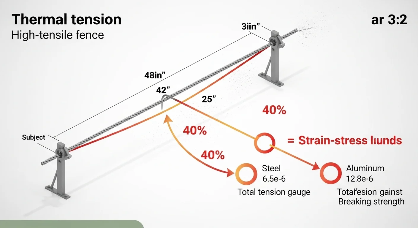
ΔT = Installation Temp − Min Winter Temp - Thermal Expansion Coefficient: Steel =
6.5 × 10⁻⁶ in/in/°F, Aluminum =12.8 × 10⁻⁶ in/in/°F - Wire Shrinkage:
Shrinkage (in) = Length (ft) × 12 × Coefficient × ΔT
This is how many inches the wire physically tries to shorten when temperature drops. - Tension Spike: Because the posts are anchored, the wire cannot actually shrink. This blocked shrinkage converts into increased tension:
Strain = Coefficient × ΔT
Stress = Young's Modulus × Strain
Tension Increase (lbs) = Stress × Wire Cross-Section Area
Steel modulus:29,000,000 psi· Aluminum:10,000,000 psi
Wire area (12.5 ga):0.007698 in² - Projected Total Tension:
Initial Tension + Tension Increase - Snap Risk: If projected tension exceeds the wire’s breaking strength, a post snap or wire break is likely. Steel 12.5 ga breaks at ~
1,350 lbs; Aluminum at ~500 lbs.
Assumptions & Limitations
- Assumes straight-line fence run with rigid, properly braced end posts.
- Wire is assumed to be standard 12.5 gauge (0.099″ diameter).
- Calculations assume no tension springs, shock absorbers, or inline tensioners are installed.
- Real-world factors such as wire sag, friction at line posts, post deflection, and crimp sleeve slippage may alter actual tension values.
- Aluminum values use 6061-T6 alloy properties; actual fence-grade aluminum may vary.
- This tool provides estimates for planning purposes. Always consult manufacturer specifications for your specific wire product.
- Temperature values should reflect air temperature, not direct sun surface temperature on the wire.
[put the tool here]
Before entering values, have the following ready: your wire manufacturer’s spec sheet (wire type and gauge), the total length of a single uninterrupted run between braced anchor assemblies, the outdoor temperature at the time of installation, and the historically recorded winter low for your property or the nearest NOAA weather station. Enter the tension you actually pulled the wire to, not a default or approximation. If you do not know your installation tension, this tool cannot give you a meaningful result.
If your fence includes corner or end-post H-brace assemblies, verify those are properly built before relying on this calculation. The H-brace fence calculator can help you confirm brace sizing for the loads this tool will identify.
Quick Start (60 Seconds)
- Wire Type: Select 12.5 Gauge High-Tensile Steel or 12.5 Gauge Aluminum. Do not guess based on color or appearance; check the spool label or spec sheet. Aluminum and steel have very different thermal behavior and breaking strengths.
- Length of Fence Run: Enter feet, not total fencing footage. Measure one continuous run between braced anchor posts. A 2,000-foot perimeter with four corners is four separate runs, typically 500 feet each, not one 2,000-foot entry.
- Installation Temperature: The actual air temperature when the wire was tensioned, in degrees Fahrenheit. Using yesterday’s temperature instead of the actual install-day temperature is a common error that shifts results by 10 to 30 lbs.
- Expected Min Winter Temperature: Use the lowest recorded temperature for your region, not the average winter low. Weather history is available through NOAA Climate Data Online. Underestimating this value is the single most common input mistake on this type of tool.
- Initial Installation Tension: The tension in pounds you set at install, measured with a calibrated fence tension meter. If you pulled the wire “hand tight” without measuring, use a conservative value of 150 lbs for aluminum and 200 lbs for steel as a working assumption, and note that your actual result may be higher.
- Run the calculation: All five fields must be filled before the Calculate button activates. If the winter temperature field is equal to or higher than your installation temperature, the tool will reject the entry.
- Read the gauge: The colored tension bar shows your result against the wire’s rated breaking strength. Any result above 75% requires action before the first hard freeze.
Inputs and Outputs (What Each Field Means)
| Field | Unit | What It Measures | Common Mistake | Safe Entry Guidance |
|---|---|---|---|---|
| Wire Type | Material selection | Determines thermal expansion coefficient, Young’s modulus, and breaking strength used in all calculations | Assuming “fence wire” is always steel; aluminum is common for game fences and some livestock applications | Verify from the spool or manufacturer’s data sheet, not visual inspection |
| Length of Fence Run | Feet (10 to 10,000) | Continuous wire span between braced anchor points; determines total shrinkage volume | Entering total perimeter footage instead of segment length between H-brace assemblies | Measure each run individually; use the longest run for worst-case analysis |
| Installation Temperature | Degrees Fahrenheit (-40 to 130) | The air temperature at the moment the wire was tensioned to its set point | Using a seasonal average rather than the actual recorded temperature on install day | Check your weather station log or a weather app with hour-by-hour history for install day |
| Expected Min Winter Temperature | Degrees Fahrenheit (-60 to 80) | The lowest temperature your wire will realistically experience after installation | Using average winter low instead of the historical extreme low for the region | Use NOAA Climate Data for your county; apply the 10-year minimum low, not the 30-year average |
| Initial Installation Tension | Pounds (50 to 500) | The wire tension set at install, as measured by a calibrated Diller or Kiwi-type fence tension meter | Guessing tension or using the same value for all wire strands regardless of position | Bottom strands typically run tighter; enter the specific strand’s measured value if calculating strand by strand |
| Projected Peak Winter Tension | Pounds (output) | Estimated total wire tension at the minimum winter temperature, combining thermal increase with initial tension | Treating this as a guaranteed value; it is a minimum estimate that excludes ice and wind loads | Add a buffer: design to 75% of breaking strength, not 99% |
| Wire Shrinkage Attempted | Inches (output) | The total linear contraction the wire is physically trying to achieve; because posts are anchored, this becomes stored tension energy | Thinking shrinkage is harmless if the wire stays in place; the anchored system converts every inch of attempted shrinkage into mechanical force | Cross-check: values above 12 inches on a single run are a strong indicator of spring or re-tensioning requirements |
| Tension Increase | Pounds (output) | The isolated thermal contribution to tension, separate from your initial set tension | Adding this to initial tension and calling the sum acceptable without comparing to breaking strength | Use the “% of Breaking Strength” output as the decision metric, not the raw pound value |
Worked Examples (Real Numbers)
Scenario 1: Summer-Built Cattle Perimeter in a Cold Climate
- Wire Type: 12.5 Gauge High-Tensile Steel
- Length of Run: 1,000 feet
- Installation Temperature: 95 degrees F (July build)
- Expected Min Winter Temperature: -10 degrees F
- Initial Installation Tension: 250 lbs
Result: Temperature differential = 105 degrees F. Wire shrinkage attempted = 8.19 inches. Thermal tension increase = 152 lbs. Projected peak winter tension = 402 lbs (29.8% of 1,350 lb breaking strength). Status: Safe.
Even a 105-degree swing on a 1,000-foot steel run stays within safe bounds at 250 lbs initial tension. The steel wire’s relatively low expansion coefficient (6.5 x 10 to the minus 6 per degree F) limits thermal tension gain to approximately 1.45 lbs per degree F. The 8 inches of attempted shrinkage sounds alarming, but because steel is stiff and the run is moderate length, the resulting force stays below the danger threshold.
Scenario 2: Aluminum Game Fence in a Mild-Winter Zone
- Wire Type: 12.5 Gauge Aluminum
- Length of Run: 500 feet
- Installation Temperature: 80 degrees F
- Expected Min Winter Temperature: 10 degrees F
- Initial Installation Tension: 150 lbs
Result: Temperature differential = 70 degrees F. Wire shrinkage attempted = 2.69 inches. Thermal tension increase = 69 lbs. Projected peak winter tension = 219 lbs (43.8% of 500 lb breaking strength). Status: Safe.
A modest 70-degree swing on a short aluminum run is manageable if initial tension is kept conservative. Aluminum’s thermal expansion coefficient is nearly double steel’s (12.8 x 10 to the minus 6), but the shorter run length limits total shrinkage, and the 150 lb initial tension leaves headroom. For runs above 1,000 feet or climates with deeper winter drops, this calculation changes substantially.
Scenario 3: Aluminum Wire Pulled Too Tight on a Long Run
- Wire Type: 12.5 Gauge Aluminum
- Length of Run: 800 feet
- Installation Temperature: 85 degrees F
- Expected Min Winter Temperature: -5 degrees F
- Initial Installation Tension: 350 lbs
Result: Temperature differential = 90 degrees F. Wire shrinkage attempted = 11.06 inches. Thermal tension increase = 89 lbs. Projected peak winter tension = 439 lbs (87.7% of 500 lb breaking strength). Status: High Risk.
This is where aluminum fencing fails in practice. The wire was built with appropriate summer tension for the application, but the combination of a 90-degree F swing, an 800-foot run, and a relatively low breaking strength puts winter tension at 87.7% of breaking strength. Any additional load, a single cold snap below -5 degrees F, ice accumulation, or animal impact, tips this fence into failure territory.
Reference Table (Fast Lookup)
All values below assume a 1,000-foot fence run with 200 lbs initial installation tension. The “Tension Increase” column represents the derived thermal contribution only. “% of Break Str” is calculated against 1,350 lbs for steel and 500 lbs for aluminum.
| Wire Type | Temp Drop (F) | Shrinkage (in) | Tension Increase (lbs) | Total Tension (lbs) | % of Breaking Str | Status |
|---|---|---|---|---|---|---|
| Steel | 30 | 2.34 | 44 | 244 | 18.1 | Safe |
| Steel | 60 | 4.68 | 87 | 287 | 21.3 | Safe |
| Steel | 90 | 7.02 | 131 | 331 | 24.5 | Safe |
| Steel | 120 | 9.36 | 174 | 374 | 27.7 | Safe |
| Aluminum | 30 | 4.61 | 30 | 230 | 46.0 | Safe |
| Aluminum | 60 | 9.22 | 59 | 259 | 51.8 | Caution |
| Aluminum | 90 | 13.82 | 89 | 289 | 57.8 | Caution |
| Aluminum | 120 | 18.43 | 118 | 318 | 63.6 | Caution |
| Aluminum | 150 | 23.04 | 148 | 348 | 69.6 | Caution |
Notice that steel at 200 lbs initial tension never exceeds 28% of breaking strength across all temperature drops shown, while aluminum enters caution territory at a 60-degree swing. The difference is not merely the expansion coefficient; aluminum’s breaking strength of 500 lbs is less than 40% of steel’s 1,350 lb rating. Both factors compound against aluminum in cold climates.
How the Calculation Works (Formula and Assumptions)

Show the calculation steps
Step 1: Temperature Differential
Subtract the minimum winter temperature from the installation temperature.
Formula: DeltaT = Installation Temp (F) minus Min Winter Temp (F)
Example: 95 F minus (-10 F) = 105 degrees F
Step 2: Thermal Expansion Coefficient
Each material has a fixed expansion coefficient per degree Fahrenheit per inch of wire length:
Steel (high-tensile): 6.5 x 10 to the minus 6 in/in/F
Aluminum: 12.8 x 10 to the minus 6 in/in/F
Step 3: Wire Shrinkage
Formula: Shrinkage (inches) = Length (ft) x 12 x Coefficient x DeltaT
This converts feet to inches, then applies thermal contraction across the full span.
Rounding: displayed to 2 decimal places; used at full precision internally.
Step 4: Thermal Tension Increase
Because the wire is constrained by anchored posts, attempted shrinkage converts to mechanical stress:
Strain = Coefficient x DeltaT
Stress (psi) = Young’s Modulus x Strain
Tension Increase (lbs) = Stress x Wire Cross-Section Area
Steel: Young’s Modulus = 29,000,000 psi; Area = 0.007698 sq in
Aluminum: Young’s Modulus = 10,000,000 psi; Area = 0.007698 sq in
Note: This calculation is independent of run length. Length affects shrinkage volume but not the per-degree tension rate.
Step 5: Projected Total Tension
Formula: Total Tension = Initial Installation Tension + Tension Increase
This is the minimum estimated tension. It does not include wind load, ice load, or animal contact forces.
Step 6: Safety Classification
Safe: below 50% of breaking strength
Caution: 50 to 75% of breaking strength
High Risk: 75 to 100% of breaking strength
Snap Risk: at or above 100% of breaking strength (failure is likely)
Assumptions and Limits
- Wire diameter is assumed to be 0.099 inches (standard 12.5 gauge), giving a cross-section area of 0.007698 square inches. Non-standard gauges will produce inaccurate results.
- Posts are assumed to be rigid and fully anchored. Post flex or soil heaving in freeze-thaw cycles reduces post resistance and may transfer some thermal tension load to adjacent line posts rather than distributing it cleanly to anchor assemblies.
- No inline tension springs, shock absorbers, or tensioners are assumed. Any installed tensioning hardware will reduce peak tension; the tool gives the worst-case result without such hardware.
- Aluminum properties reflect general 6061-T6 alloy characteristics. Fence-grade aluminum alloys vary by manufacturer; actual breaking strength and modulus may differ by up to 15%.
- Temperature is assumed to be uniform along the entire wire run. In practice, shaded sections cool faster and may experience localized tension spikes before the system equilibrates.
- Crimp sleeve performance is not modeled. A properly seated Nicopress crimp rated to the wire spec will hold rated tension; an under-crimped sleeve can slip at 60 to 70% of rated wire tension, causing a localized tension spike that the formula does not capture.
- This tool applies only to single straight runs of uniform wire between two braced anchor assemblies. Curved alignments, topographic changes, and multi-strand configurations require additional analysis.
Standards, Safety Checks, and “Secret Sauce” Warnings
Critical Warnings
- The “Summer-Tight” Setup: Installing wire at full specified tension during warm months is the most common cause of winter fence failure. The wire is correctly tensioned at install. The failure happens months later when the temperature drops and tension spikes beyond what the system was designed for. This tool exists specifically to catch that scenario before it happens.
- Aluminum’s Hidden Vulnerability: Aluminum wire expands and contracts at nearly twice the rate of steel per degree F, and its breaking strength is less than 40% of comparable steel wire. On runs above 800 feet in climates with 80-degree F or greater seasonal temperature swings, aluminum fence wire is structurally at risk even at conservative installation tensions. The reference table in this page quantifies this clearly.
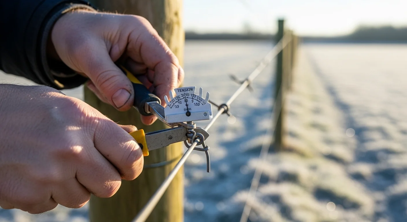
- Tension Meter Readings Are Point-in-Time: A tension meter confirms the tension that existed at the moment of measurement. It tells you nothing about what that tension will become at 2 a.m. on the coldest night of January. Running this calculator before and after installation with your recorded tension values closes that information gap.
- Crimp Sleeve Failure Mode: Nicopress and other crimp-style connections are rated to full wire breaking strength only when properly seated with the correct die. An under-crimped sleeve will slip at a fraction of rated wire tension, releasing tension abruptly and sometimes creating a whipping hazard. Inspect all splices before winter.
Minimum Standards
- Target a maximum projected winter tension at or below 75% of the wire’s rated breaking strength. This provides a safety margin for temperature extremes below your estimate and additional mechanical loads.
- For steel high-tensile fence wire on runs exceeding 1,500 feet, inline tension springs installed every 500 to 1,000 feet are an industry best practice in climates where temperature swings exceed 80 degrees F.
- All braced anchor assemblies should be designed to handle the wire’s full breaking strength in tension, not the installation tension. Thermal tension can approach breaking strength; the post must be capable of absorbing that load.
Competitor Trap: Most fence-wire guides and online resources describe how to tension high-tensile wire correctly at installation. Very few address what happens to that tension six months later when the temperature drops 100 degrees F. The standard advice to “use a tension meter” is correct but incomplete. A tension meter reads current tension. It has no ability to forecast winter tension based on thermal physics. Builders who follow standard tensioning protocols without modeling seasonal thermal effects are creating a structurally correct installation for July that may be a structurally compromised installation for January. This calculator fills that gap by extending the tension meter reading forward in time using the wire’s material properties and the expected temperature floor.
If you are comparing wire options, the woven wire fence calculator can help you evaluate material quantities for alternative fence configurations, while pasture planning tools like the pasture stocking rate calculator can inform how many fence runs your land management plan actually requires before you commit to a wire type.
Common Mistakes and Fixes
Mistake: Using Total Perimeter Length Instead of Run Length
A 4,000-foot rectangular pasture perimeter has four corners, each requiring a braced assembly. That creates four independent runs of approximately 1,000 feet each, not one 4,000-foot run. Entering 4,000 feet as the run length produces a shrinkage value four times larger than reality, which may flag a safe fence as a critical failure.
Fix: Measure and enter the longest single span between braced anchor points, not total fencing footage.
Mistake: Ignoring the Difference Between Average Winter Low and Recorded Extreme Low
Climate averages smooth out the years when January drops 15 degrees colder than typical. The wire does not experience averages; it experiences specific nights. Using the 30-year average low temperature for your region will underestimate the true thermal load the fence must carry.
Fix: Look up the 10-year absolute minimum temperature for your county through NOAA Climate Data Online and use that value as your minimum winter input.
Mistake: Assuming Both Wire Types Behave Similarly
Steel and aluminum look similar as bare wire and are both sold in 12.5 gauge. Their thermal and mechanical properties, however, are substantially different. Aluminum expands and contracts at 1.97 times the rate of steel per degree F, and its breaking strength for 12.5 gauge is approximately 500 lbs compared to 1,350 lbs for steel. Substituting aluminum for steel in a design that was thermally calculated for steel will fail the winter analysis in most cold climates. For rotational grazing systems where fence lines are moved seasonally, this distinction becomes critical; the rotational grazing calculator can help you scope how many fence runs your grazing system requires and where permanent versus portable fencing makes sense.
Fix: Run this calculator separately for each wire type you are comparing before purchasing material.
Mistake: Setting Initial Tension Too High “To Be Safe”
Some installers reason that tighter is better for livestock containment, so they pull wire to 300 or 350 lbs on aluminum runs that are rated for much lower working tensions. Higher initial tension reduces the thermal headroom available before the wire approaches breaking strength. A wire set at 350 lbs with a 500 lb breaking strength has only 150 lbs of thermal budget before failure. At 90 degrees F of swing, an aluminum wire consumes 89 of those lbs. The arithmetic leaves almost no margin for any additional load.
Fix: Follow manufacturer recommended installation tension ranges, which are designed to leave thermal and mechanical headroom. For aluminum, this is typically 100 to 150 lbs on long runs.
Mistake: Skipping the Calculation Because the Fence “Survived Last Year”
Fence wire fatigue accumulates over multiple thermal cycles. A wire that carried 85% of its breaking strength through two winters may be measurably work-hardened and more brittle going into year three. Surviving does not mean safe; it means the failure has not occurred yet. Additionally, last year’s winter low may not have been the design extreme for your region.
Fix: Run this calculation every time you install new wire or when you record your region’s coldest winter temperature in memory. Use the most extreme low as your baseline, not the most recent.
Next Steps in Your Workflow
Once your projected winter tension is confirmed as safe, the next structural variable to verify is your energizer’s output relative to the fence length and load. Fence tension affects wire-to-ground clearance at each line post, and clearance changes affect the energizer’s effective voltage delivery. The electric fence joule calculator can help you confirm your energizer is appropriately sized for your total wire length, number of strands, and expected vegetation contact.
If your calculation returns a Caution or High Risk result, the most practical mitigation before the first hard freeze is installing inline tension springs rated for your wire type. Springs inserted every 500 to 1,000 feet absorb a portion of the thermal contraction and prevent the tension from reaching the static value this tool predicts. After springs are installed, re-enter your run length as the segment length between springs rather than the total run. This recalculation will typically confirm the springs have moved your result back into the safe zone. For larger livestock operations planning how many fence runs to build, the rotational grazing planning tool can help you determine how much fencing your system actually needs before you commit material and labor to runs that this thermal analysis identifies as problematic.
FAQ
Why does wire length affect shrinkage but not the tension increase per degree?
Shrinkage in inches is a product of length because more wire means more total material contracting. But the tension increase is determined by the material’s stiffness (Young’s modulus) and its thermal expansion coefficient, which are material constants unaffected by length. A longer wire develops more shrinkage in absolute terms but the same tension increase per degree Fahrenheit, because every inch of that wire is under the same mechanical constraint.
Is this calculation valid for multiple strands of wire on the same fence?
Yes, but calculate each strand separately if they have different initial tensions. A typical multi-strand fence runs bottom strands tighter than top strands. Each strand’s thermal tension increase is identical given the same material and temperature, but the total projected tension for each strand differs based on its individual starting tension. The weakest link is the strand closest to its breaking strength.
What happens if I install inline tension springs?
Tension springs allow the wire to physically contract by a limited amount, absorbing some of the thermal shrinkage instead of converting it all to tension. After installing springs, you should recalculate treating each spring-segmented span as a separate run. The effective run length for the calculation becomes the segment between the spring and the nearest anchor, not the full original run length.
Does wind or ice load change these results?
This tool calculates thermal tension only. Wind load, ice accumulation, and animal contact all add to the projected tension value. The output here is therefore a minimum estimate under pure thermal conditions. In regions with regular ice storms or strong prevailing winds against fence lines, the actual peak tension during a winter event will exceed the tool’s output. Treat the tool result as a floor, not a ceiling.
My fence survived 10 winters. Does this calculation still matter?
Repeated high-tension thermal cycles accumulate wire fatigue. Steel wire that has cycled near its breaking strength multiple times develops micro-fractures and reduced ductility over time. A wire that appeared fine on visual inspection may fail at a lower actual breaking strength than the rated value. Past survival is not a substitute for thermal analysis; it is an argument for doing it sooner rather than later.
Can I use this for barbed wire or field fence?
The underlying thermal physics applies to any steel or aluminum wire. However, this tool is calibrated specifically for 12.5 gauge high-tensile wire with its known modulus, cross-section area, and breaking strength. Standard barbed wire (typically 12.5 or 14 gauge but lower tensile grade), field fence, and woven wire have different breaking strengths and sometimes different modulus values. Using this tool for non-high-tensile wire will give you shrinkage values that are correct but tension-spike and safety classifications that do not apply to the lower-grade wire’s rating.
Conclusion
The physics of high-tensile wire under thermal load is deterministic. Given material type, run length, installation temperature, winter low, and starting tension, the projected peak winter tension is calculable in advance, before the first freeze. The gap between “correctly tensioned at installation” and “structurally overloaded in January” is not a matter of luck or installation skill. It is a matter of whether anyone ran the numbers before the wire went up.
The single most important variable to get right is the minimum winter temperature input. Underestimating by 10 degrees F does not create a small error; on a long aluminum run, it can be the difference between a Caution and a High Risk result. Use recorded historical extremes for your region, not averages, and re-run this calculation any time you are building in a new climate or specifying wire for a client’s property rather than your own. For operations building out comprehensive perimeter and interior fencing systems, pairing this tool with the H-brace fence calculator ensures that the anchor assemblies holding your thermally loaded wire are sized to handle the actual forces this tool identifies.
Lead Data Architect
Umer Hayiat
Founder & Lead Data Architect at TheYieldGrid. I bridge the gap between complex agronomic data and practical growing, transforming verified agricultural science into accessible, mathematically precise tools and guides for serious growers.
View all tools & guides by Umer Hayiat →