Staking a newly planted tree looks simple. Drive two or three stakes, run wire between them and the trunk, and the tree stands straight. What that picture misses is the physics beneath the surface: the relationship between wind speed, canopy area, anchor angle, and tensile load determines whether your hardware holds or fails on the first storm. It also misses the slower failure mode, where wire that was installed too tight progressively cuts through the cambium layer, strangling the tree over one to three growing seasons long after the crew has moved on.
This calculator estimates wind-driven force on a newly planted tree, derives the required guy wire tension per stake, positions the anchor at the correct distance from the trunk, and enforces the mandatory two-inch slack rule that keeps wire from becoming a tourniquet. It does not replace a licensed arborist for specimen trees, structurally deficient sites, or hurricane-zone installations. If your project involves preserving a large existing tree’s root zone, the tree root protection calculator addresses ground disturbance constraints near anchor installation zones.
After running your inputs, you will know how many anchors to install, exactly how far from the trunk to drive them, what tension rating each strap must meet, and how long each wire needs to be including slack. That output is the staking plan. Execute it before planting, not after.
Use the Tool
Tree Staking & Wind Load Calculator
Guy wire tension, anchor placement & safety analysis
| Wind Speed | Category | Est. Force (this tree) | Risk |
|---|
How This Calculator Works
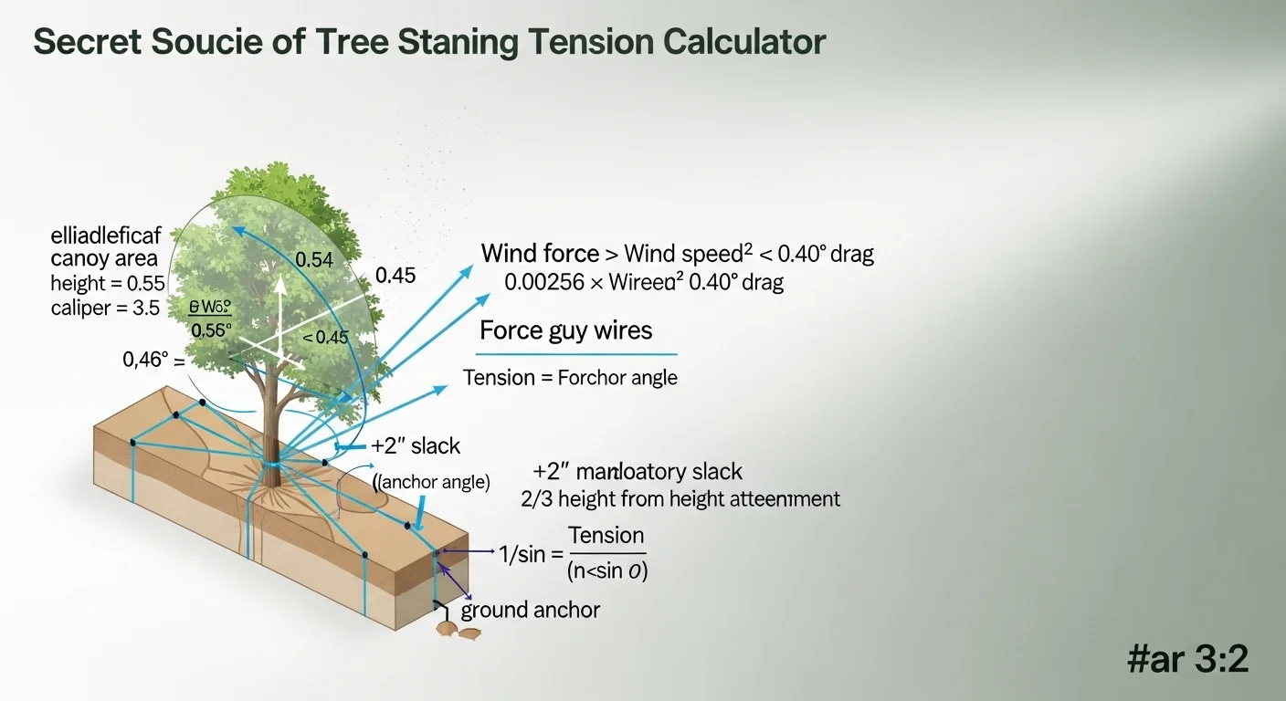
Step 1 — Estimate Canopy Area: The canopy is modeled as an ellipse based on tree height and caliper. Canopy width ≈ caliper × 3.5 feet. Canopy height ≈ treeHeight × 0.55. Canopy area ≈ π × (canopyWidth / 2) × (canopyHeight / 2) square feet.
Step 2 — Calculate Wind Force: Using a simplified drag equation: WindForce (lbs) = 0.00256 × WindSpeed² × DragCoeff × CanopyArea. Drag coefficient for a broadleaf canopy is assumed at 0.40.
Step 3 — Anchor Distance: Target anchor distance = TreeHeight × 0.60 feet from the trunk base, measured at ground level.
Step 4 — Per-Stake Tension: Total wind force is divided among the number of stakes (3 typical). Tension per line accounts for the guy wire angle: tension = (windForce / numStakes) / sin(angle).
Step 5 — Guy Wire Length: Geometric wire length from attachment point (⅔ trunk height) to anchor, plus mandatory 2 inches of slack to allow healthy trunk sway.
Step 6 — Safety Checks: If anchor angle < 45°, holding power decreases. The tool warns if the angle is too shallow. Drum-tight wires cause girdling — wires must always have slack.
Assumptions & Limits
- Canopy modeled as a porous ellipse (deciduous tree with leaves); conifer or bare trees will have less wind load.
- Drag coefficient of 0.40 assumes a typical broadleaf crown; dense evergreens may reach 0.50+.
- Soil is assumed firm (non-saturated clay or loam); sandy or wet soil reduces anchor holding capacity.
- For B&B (balled-and-burlapped) trees, rootball weight provides additional anchoring not included in this calculation.
- Calculator assumes 3 guy wires at 120° spacing; 2-stake systems are weaker and only suited for calm regions.
- Wind gusts are instantaneous peaks; sustained wind loads are typically 60–70% of gust force.
- Staking should be removed after 1 growing season (typically 12 months) to prevent dependency.
Before you enter values, have four measurements ready: total tree height from root flare to highest leader tip (in feet), trunk caliper measured six inches above the root flare (in inches), the peak wind gust speed for your site from a local weather history or county design wind map (in mph), and the angle from the ground at which you plan to drive each anchor stake (in degrees). If you have not yet confirmed your tree's exact height, the tree height calculator can help you estimate from shadow or clinometer readings before your nursery delivery arrives.
Quick Start (60 Seconds)
- Tree Height (ft): Measure from root flare to the topmost leader, not from ground to first branch. Accepted range is 2 to 80 ft. Balled-and-burlapped trees are often listed by height at the nursery; confirm the tag matches actual measurement.
- Trunk Caliper (in): Use calipers or a diameter tape at exactly 6 inches above the root flare. Do not measure at soil grade; nursery soil often buries the flare, giving a falsely large reading.
- Peak Wind Gusts (mph): Use the highest recorded gust for your site, not the average wind speed. NOAA storm data and county ASCE 7 wind maps are the correct sources. Underestimating wind is the single most common reason stakes pull out.
- Anchor Stake Angle (degrees): This is the angle of the stake shaft measured from horizontal ground. A vertical stake (90 degrees) resists uplift poorly. Between 45 and 60 degrees is the target zone. Below 45 degrees, the holding power calculation includes a automatic warning.
- Units must match: Heights in feet only. Caliper in decimal inches (a 2.5-inch tree is entered as 2.5, not as 2 1/2). Wind in mph, not km/h or knots.
- Do not guess caliper: A 1-inch caliper error propagates directly into canopy area and wind force estimates. Measure twice.
- Click "Calculate Staking Plan" only after all four fields pass validation. The results panel will not update if any field contains an error.
Inputs and Outputs (What Each Field Means)
| Field | Unit | What It Represents | Common Entry Mistake | Safe Entry Guidance |
|---|---|---|---|---|
| Tree Height | Feet | Total height from root flare to leader tip; used to estimate canopy dimensions and determine attachment height at two-thirds of total height | Using height to first branch instead of total height; understates canopy mass by 30 to 50 ft on large shade trees | Measure to the topmost tip; accepted range 2 to 80 ft |
| Trunk Caliper Diameter | Inches | Trunk cross-section diameter 6 inches above root flare; proxy for canopy width because canopy width scales with caliper in broadleaf trees | Measuring at grade rather than 6 inches up; soil-buried flares add 0.5 to 1.5 inches of false reading | Expose and locate the true flare first; accepted range 0.5 to 24 in |
| Peak Wind Gusts | mph | Maximum instantaneous gust speed expected at the site; drives the wind force calculation quadratically (doubling wind speed quadruples force) | Using average wind speed instead of peak gust; average is typically 55 to 65 of peak gust | Source from NOAA storm data or ASCE 7 county maps; accepted range 5 to 150 mph |
| Anchor Stake Angle | Degrees | Angle of the stake shaft from the horizontal ground plane; determines how much of the tensile load converts into vertical holding resistance versus horizontal sliding resistance | Assuming a vertical stake (90 degrees) gives the best hold; vertical stakes resist uplift, not horizontal pull | Target 45 to 60 degrees from horizontal; accepted range 15 to 90 deg |
| Wind Force (output) | lbs | Estimated total lateral load on the canopy derived from drag equation using canopy area and wind speed | Treating this as the load each stake carries; it is the TOTAL load split across all stakes | Verify against the per-stake tension output, which accounts for the number of anchors and angle |
| Anchor Distance (output) | Feet from trunk | Required horizontal distance from trunk base to each anchor stake, set at 60 of tree height | Measuring anchor distance from the rootball edge instead of trunk center | Always measure from trunk center; mark with spray paint before backfilling |
| Wire Tension / Stake (output) | lbs per line | Load each individual guy wire must withstand; accounts for angle and number of stakes | Buying straps rated at the total load rather than per-wire load; leads to over-engineered or under-rated hardware | Select hardware rated above this output; flat nylon straps are safest for cambium protection |
| Guy Wire Length (output) | Feet | Geometric wire length from trunk attachment to ground anchor including mandatory two-inch slack | Cutting wire at the exact geometric length, leaving no slack; creates drum-tight conditions guaranteed to girdle | Order wire at this length or slightly longer; always install with visible sag in the line |
| Recommended Stakes (output) | Count | Number of guy lines recommended; defaults to 3, increases to 4 for high-load scenarios above 150 lbs total force | Installing only 2 stakes because it looks cleaner; two-stake systems leave one direction completely unresisted | Use the recommended count; space equally around the trunk at uniform angles (120 degrees for 3, 90 degrees for 4) |
Worked Examples (Real Numbers)
Scenario 1: Small Ornamental Tree in a Suburban Yard
- Tree Height: 8 ft
- Trunk Caliper: 1.5 in
- Peak Wind Gusts: 35 mph
- Anchor Stake Angle: 45 degrees
Estimated canopy area: 18.2 sq ft. Wind force: 22.8 lbs.
Result: 3 anchors at 4.8 ft from trunk, 10.7 lbs tension per line, 7.3 ft wire length with slack.
A light-duty scenario. Standard 1-inch flat nylon tree straps rated at 25 lbs each exceed the per-line load. Duckbill No. 38 earth anchors at 45 degrees provide well above the required holding capacity in firm loam.
Scenario 2: Medium Shade Tree, Windy Open Site (B&B Planting)
- Tree Height: 18 ft
- Trunk Caliper: 3.5 in
- Peak Wind Gusts: 60 mph
- Anchor Stake Angle: 45 degrees
Estimated canopy area: 95.4 sq ft. Wind force: 351.7 lbs.
Result: 4 anchors at 10.8 ft from trunk, 124.3 lbs tension per line, 16.3 ft wire length with slack.
At 60 mph gusts on an 18 ft tree, per-line tension exceeds 75 lbs, triggering the strap-rating warning. Two-inch flat nylon straps rated at 200 lbs breaking strength are the minimum. Duckbill No. 68 anchors or 36-inch helical ground anchors are appropriate. This is not a job for wooden stakes.
Scenario 3: Large Specimen Tree in a Storm-Prone Region
- Tree Height: 28 ft
- Trunk Caliper: 5 in
- Peak Wind Gusts: 45 mph
- Anchor Stake Angle: 60 degrees
Estimated canopy area: 211.7 sq ft. Wind force: 438.8 lbs.
Result: 4 anchors at 16.8 ft from trunk, 126.7 lbs tension per line, 25.3 ft wire length with slack.
Even at 45 mph, a 28 ft canopy generates over 400 lbs of lateral force. The 60-degree anchor angle improves holding capacity versus 45 degrees. Hardware procurement should use rated turnbuckles and arborist-grade webbing straps. At this scale, a certified arborist inspection at 3-month intervals is advisable.
Reference Table (Fast Lookup)
| Wind Speed (mph) | Tree Height (ft) | Caliper (in) | Est. Wind Force (lbs) | Recommended Stakes | Tension / Stake at 45 deg (lbs) | Anchor Distance (ft) | Risk Level |
|---|---|---|---|---|---|---|---|
| 25 | 8 | 1.5 | 11.6 | 3 | 5.5 | 4.8 | Low |
| 30 | 12 | 2.0 | 33.5 | 3 | 15.8 | 7.2 | Low |
| 35 | 8 | 1.5 | 22.8 | 3 | 10.7 | 4.8 | Low |
| 45 | 12 | 2.0 | 75.3 | 3 | 35.4 | 7.2 | Moderate |
| 50 | 20 | 3.0 | 232.2 | 4 | 82.0 | 12.0 | High |
| 55 | 15 | 2.5 | 175.8 | 4 | 62.1 | 9.0 | High |
| 60 | 18 | 3.5 | 351.7 | 4 | 124.3 | 10.8 | High |
| 65 | 18 | 3.0 | 353.8 | 4 | 125.1 | 10.8 | High |
| 80 | 10 | 2.0 | 198.4 | 4 | 70.1 | 6.0 | High |
| 45 | 28 | 5.0 | 438.8 | 4 | 155.1 | 16.8 | High |
All tension values assume a 45-degree anchor angle and the number of stakes shown. Increasing angle to 60 degrees reduces per-stake tension by approximately the ratio of sin(45) to sin(60). Soil type is not factored into this table; sandy or saturated soils reduce anchor holding capacity and require longer or wider anchors.
How the Calculation Works (Formula + Assumptions)

Show the calculation steps
Step 1: Canopy Area Estimate
Canopy width (ft) = trunk caliper (in) x 3.5
Canopy height (ft) = tree height (ft) x 0.55
Canopy area (sq ft) = pi x (canopy width / 2) x (canopy height / 2)
This models the crown as an ellipse. Rounding: carry four decimal places through intermediate steps; round final area to one decimal place.
Step 2: Wind Force (Drag Equation)
Wind force (lbs) = 0.00256 x wind speed (mph) squared x drag coefficient x canopy area (sq ft)
The constant 0.00256 converts mph squared into dynamic pressure in lbs per sq ft (equivalent to 1/2 x air density at sea level). The drag coefficient is fixed at 0.40 for a porous broadleaf crown in full leaf. Final wind force is rounded to one decimal place.
Step 3: Anchor Distance
Anchor distance (ft) = tree height (ft) x 0.60
This keeps the guy wire angle geometry appropriate for the recommended attachment height and limits the wire angle to a functional range regardless of tree size.
Step 4: Attachment Height
Wire attachment point on trunk (ft) = tree height x (2/3)
Attaching at two-thirds height places the load at approximately the tree's center of wind pressure for a typical broadleaf crown.
Step 5: Wire Tension Per Stake
Tension per stake (lbs) = (total wind force / number of stakes) / sine of anchor angle (degrees)
The sine function converts horizontal tensile load into the diagonal wire load required to produce that resistance. At 45 degrees, sine = 0.707, so tension per wire is 41 higher than the raw per-stake share. At 30 degrees, sine = 0.500, doubling the wire tension for the same load.
Step 6: Guy Wire Length with Slack
Geometric wire length (ft) = square root of (attachment height squared + anchor distance squared)
Final wire length (ft) = geometric length + 2 inches (converted to 0.167 ft)
The 2-inch slack addition is not cosmetic; it is a biomechanical minimum that allows the trunk to flex under load, triggering the hormonal response that builds taper and structural wood.
Assumptions and Limits
- Drag coefficient 0.40 represents a typical deciduous tree in full leaf. Conifers, or bare deciduous trees in winter, may fall closer to 0.30 or as high as 0.50 for dense evergreens.
- Air density is modeled at sea level. At elevations above 5,000 ft, air is thinner and wind force drops by roughly 15 to 20 lbs per 1,000 ft of elevation gain at constant wind speed.
- The canopy ellipse model underestimates force on trees with spreading, low crowns (such as many oaks) and overestimates it on narrow, upright columnar forms.
- Soil anchor holding capacity is not computed. Sandy soil, saturated clay after heavy rain, and recently disturbed backfill all reduce the force an anchor can resist, sometimes by more than half compared to firm native soil.
- The rootball weight of balled-and-burlapped trees provides additional overturning resistance not included in this calculation. The output is therefore conservative for B&B planting.
- Three-stake spacing is assumed at 120-degree intervals. Off-angle placement (not equally spaced) reduces the system's ability to resist wind from all directions.
- The calculator does not model resonance or oscillation effects. In sustained wind events, trees can develop oscillation that progressively loosens stake connections; periodic inspection after storms is always required.
- This tool is not a substitute for an arborist's site assessment on trees over 30 ft, on structurally compromised specimens, or in locations with exposure ratings above Design Wind Zone C.
Standards, Safety Checks, and "Secret Sauce" Warnings
Critical Warnings
- Girdling Wire is the Leading Cause of Avoidable Tree Death After Planting: When wire is pulled drum-tight around a trunk, it does not stay still. As the tree rocks in wind, the wire saws against the cambium, the thin living layer just inside the bark responsible for water and nutrient transport. Cambium damage is irreversible. A tree can lose vascular continuity over a single growing season without showing obvious symptoms until it collapses. The mandatory two-inch slack in every guy wire is not a suggestion; it is the minimum threshold between a healthy installation and a slow-motion kill.
- Anchor Angle Below 45 Degrees Reduces Holding Power Sharply: The sine function governing tension per stake drops from 0.707 at 45 degrees to 0.500 at 30 degrees. That means a stake at 30 degrees must carry twice the wire tension of a stake at 45 degrees for identical loading conditions. Shallow angles also increase the risk of stake walk, where repeated loading gradually lifts the stake out of the ground. If site conditions force a shallow angle, switch to helical earth anchors or Duckbill-style deadman anchors rated for the computed tension.
- Remove All Staking Hardware Within 12 Months: Stakes left beyond one growing season cause the tree to stop investing in structural wood because mechanical support substitutes for the environmental signal that drives taper. A tree staked for two or more years typically has a trunk cross-section 20 to 40 lbs weaker at the attachment zone than a tree that developed freely. The tree age calculator can help you log the planting date and set a removal reminder based on species-typical establishment timelines.
- Never Use Bare Metal Wire Directly Against Bark: Even soft copper wire exceeds the cambium's tolerance for cyclical abrasion. The tool outputs a tension value; that value must be carried by a flat nylon or rubber-padded strap, with wire or cable only connecting the strap to the anchor. Use a figure-eight or loop around the strap to distribute load across bark area rather than concentrating it on a wire contact point.
Minimum Standards
- Attach guy wires at no lower than two-thirds of total tree height; lower attachment points concentrate bending load at the root flare and can cause caliper splitting in large B&B trees.
- Space anchors equally around the trunk; unequal spacing leaves directional wind exposure gaps that a three-stake system cannot resist.
- Inspect all connections within 72 hours of any wind event exceeding 40 mph; re-tension or replace any line that has lost its two-inch slack allowance.
- For fence post-style wooden stakes, confirm the stake depth matches the resistance required for the computed tension. The fence post depth calculator provides a useful parallel check for stake embedment relative to lateral load.
Competitor Trap: The majority of staking guides online show two stakes and a single wire looped through a garden hose. That system resists wind from only one axis, leaves the perpendicular axis completely unresisted, and the hose section does not distribute load across enough cambium surface area to prevent abrasion in trees over 1-inch caliper. It is a technique optimized for visual tidiness, not structural function. On any tree above 10 ft in a region with gusts above 30 mph, a two-stake hose-and-wire system has a meaningful failure probability in the first storm season. This calculator defaults to three stakes at minimum, four for higher loads, and the geometry reflects actual wind loading rather than installer convenience.
Common Mistakes and Fixes
Mistake: Measuring Wind Speed from a Nearby Airport Rather than the Planting Site
Airport anemometers sit on open tarmac at specific heights and are corrected for aviation use, not ground-level landscape wind. A planting site surrounded by open lawn or on a slope can experience gusts 15 to 25 mph higher than the nearest aviation reporting station. Using airport data consistently underestimates loading for exposed sites. Fix: use NOAA's storm events database for historical peak gusts at the ZIP code level, or consult the county's ASCE 7 design wind map for code-level gust speeds.
Mistake: Installing Anchors in the Critical Root Zone
Driving stakes within the critical root zone damages feeder roots that the tree needs to establish. On a newly planted 3-inch caliper tree, the critical root zone radius can extend 3 to 5 ft beyond the rootball edge, which may conflict with anchor placement distances on small sites. The critical root zone calculator provides precise radius figures by caliper and species group. Fix: if anchor distance conflicts with root zone, use surface deadman anchors or non-penetrating ballast plates instead of driven stakes.
Mistake: Cutting Wire to the Exact Geometric Length
The geometric length from attachment height to ground anchor is the minimum wire needed to reach, not the correct installation length. Cutting at geometric length produces a drum-tight installation by definition, because the wire carries full tension before any sag develops. Every installer who cuts wire to length and thinks they will "leave a little slack" underestimates how much tension the first moderate wind will remove from that slack margin. Fix: add a minimum of two inches, then check the installed wire by hand; you should be able to push two fingers between the wire and the trunk without force.
Mistake: Using the Same Hardware for All Tree Sizes
A box of 0.5-inch diameter stakes and 14-gauge wire works for a 6-ft ornamental but fails structurally on an 18-ft shade tree at 55 mph. The reference table on this page shows that per-stake tension can range from under 10 lbs to over 125 lbs within the normal planting size range. At 125 lbs, 14-gauge wire is operating at or near its tensile limit, and a wooden stake provides negligible holding capacity. Fix: check the tension output before purchasing hardware and specify strap and anchor ratings that exceed the calculated value.
Mistake: Forgetting Stake Removal Entirely
A tree that is staked and forgotten develops girdling damage silently. The first visible symptoms, crown dieback or sudden lean, often appear two to three years after installation when the damage is already irreversible. The wire that has been cutting into the cambium since year one has already interrupted vascular flow before the trunk shows visible constriction. Fix: set a calendar reminder at 10 months after planting. Walk the tree, cut all wires, remove all stakes, and confirm the trunk is free of any contact marks. If constriction is visible, contact a certified arborist immediately.
Next Steps in Your Workflow
Once you have the staking plan from this calculator, transfer the anchor distance measurement to the planting site before the tree arrives. Mark each anchor point with a pin flag at the computed distance from the planting hole center, at equal angular spacing around the circle. Driving anchors into undisturbed native soil before the rootball is placed gives you superior holding capacity compared to installing into the disturbed, loosely backfilled area adjacent to a freshly planted rootball. Lay out the guy wires loose across the soil so the installation crew does not have to improvise lengths at the end of the job. After backfilling and watering the rootball in, top the planting zone with the correct mulch depth, avoiding direct contact with the trunk flare; the mulch calculator helps determine the cubic footage of material needed based on ring dimensions.
At the 90-day mark, inspect the installation. Check that each wire still has two inches of slack, look at the strap contact points on the bark for any compression ridges, and confirm no anchor stake has migrated. On heavy-clay or sandy sites, use the topsoil calculator to plan an amended backfill mix if the native soil has poor drainage or structural instability that might affect anchor holding capacity over time. At 12 months, remove all hardware unconditionally. The tree's own structural wood is now the support system, which is exactly how it was designed to work.
FAQ
How many stakes does a newly planted tree need?
Three equally spaced stakes are the minimum for trees over 6 ft in height because they resist wind from all directions. Two stakes leave the perpendicular axis unresisted. Four stakes are appropriate when the calculator's wind force output exceeds 150 lbs, which typically occurs on trees above 15 ft in regions with gusts over 50 mph. Spacing the stakes at equal angular intervals around the trunk is as important as the count.
What angle should tree stakes be driven at?
The optimal installation angle is between 45 and 60 degrees from horizontal. At 45 degrees, holding power is roughly balanced between resisting vertical uplift and horizontal pull. Below 45 degrees, per-wire tension increases sharply due to the sine function in the load formula, and the stake is more likely to walk progressively upward under repeated load cycling. Above 70 degrees, the stake resists uplift efficiently but loses horizontal resistance.
Why does the calculator require two inches of slack in the guy wire?
Trunk sway in wind is not a problem to prevent; it is a required physiological process. Lateral movement triggers the release of ethylene and redirects auxin flow, both of which stimulate the production of reaction wood that builds trunk taper and mechanical strength. A drum-tight wire eliminates this movement, and the tree never develops the structural wood it needs to stand independently when the stakes are removed. Two inches of slack preserves enough movement to maintain that signaling pathway.
Can bare wire be used if it is wrapped in garden hose?
Garden hose reduces abrasion compared to bare wire but does not eliminate it, and it obscures the contact point from visual inspection. As the hose degrades, UV-cracked sections can cut bark as effectively as bare wire. Flat nylon webbing straps distribute the load over a wider surface area, reduce localized bark compression, and are visually inspectable. They are the recommended hardware regardless of tree size.
How far from the trunk should anchors be placed?
The formula used in this calculator places anchors at 60 of total tree height measured horizontally from the trunk base. For a 12-ft tree, that is 7.2 ft. This distance maintains an appropriate guy wire angle given the two-thirds attachment height. Placing anchors too close steepens the wire angle toward vertical, which shifts load from tensile resistance into trunk compression. Placing anchors too far shallows the angle and reduces holding efficiency.
When should tree stakes be removed?
Remove all staking hardware at the end of the first full growing season, typically 10 to 14 months after planting. Trees that are staked into a second season become mechanically dependent: the trunk does not invest in structural wood at the attachment zone because the wire is providing support instead. Stakes should stay on only as long as the rootball requires assistance staying anchored during establishment, not longer. If the tree leans significantly after removal, consult a certified arborist before re-staking.
Conclusion
The physical relationship between wind speed, canopy area, anchor angle, and tensile load is not complicated, but it is precise enough that guessing at hardware and distances produces real failures. This calculator converts those four inputs into a staking plan with specific numbers for anchor placement, strap load rating, and wire length. The most important number is not the wind force figure; it is the two-inch slack requirement that the output enforces on every wire length. That single detail separates a properly installed system that supports establishment from one that silently destroys the cambium while the tree appears healthy.
The mistake that causes the most preventable tree loss after planting is not under-specification of hardware. It is drum-tight wire left on too long. Install with slack, inspect at 90 days, and remove at 12 months without exception. For projects where the planting hole area itself is constrained by paving or structural features, the planter weight calculator can help assess whether a contained planting environment can support the rootball mass and anchor forces involved in above-grade installations.
Lead Data Architect
Umer Hayiat
Founder & Lead Data Architect at TheYieldGrid. I bridge the gap between complex agronomic data and practical growing, transforming verified agricultural science into accessible, mathematically precise tools and guides for serious growers.
View all tools & guides by Umer Hayiat →
Hydrangea Pruning: Match Your Cuts to Bloom Wood Type for Reliable Flowers Every Year
The real difference between hydrangeas that bloom year after year and those that skip a season comes down to one decision: does your plant set its flower…
Spring Bulbs Decision Grid: 9 Naturalizing Varieties for Multi-Year Color in Your Garden
Spring bulbs deliver the most value when selected for their ability to naturalize and multiply in place rather than serving as one-season displays that fa…
Cut Flower Garden: 12 Plants That Regenerate After Every Harvest
A cut flower garden succeeds when every stem you cut triggers new growth from side shoots or the base rather than ending the plant’s season. Most recommen…
Butterfly Flowers: The Yield Grid Decision Grid for Choosing Plants That Match Your Conditions
Butterfly flowers deliver consistent visitors only when selected through a conditions-based grid rather than popularity rankings that overlook invasivenes…
