Voltage loss along an electric fence wire is not random. It follows a predictable relationship between wire resistance, energizer output, and total run length. Most fence problems that look like energizer failures are actually resistance problems: the wrong wire gauge for the distance, corroded connections adding hidden ohms, or an undersized energizer trying to push current through a load it was never rated for. Measuring at the energizer and concluding the fence is fine is one of the most common diagnostic errors in livestock management.
This tool calculates estimated end-of-fence voltage using wire resistance values for steel and aluminum at three common gauges, combined with your energizer’s rated output voltage and stored energy. It models the voltage divider relationship between the energizer’s effective internal impedance and the wire’s total resistance to estimate how many volts actually reach the far end of your fence. What it does not model: ground fault leakage from vegetation contact, insulator failures, joint corrosion, or multi-strand configurations. Those factors typically reduce real-world voltage further than this calculation predicts.
Bottom line: Run the calculator before buying a new energizer. If the math shows your current energizer should deliver adequate voltage but your voltmeter says otherwise, the problem is a ground fault or connection issue, not an underpowered energizer. That distinction saves time and money.
Use the Tool

Electric Fence Voltage Drop Calculator
The Yield Grid — Homesteading & Livestock Tool
| Length (ft) | Wire Type | Resistance (Ω) | Voltage Drop (V) | End Voltage (V) | Rating |
|---|
How This Calculator Works
Formula Steps
- Wire Resistance: R (Ω) = Fence Length (ft) × (Ohms per 1,000 ft for selected gauge ÷ 1,000)
- Drive Current Estimate: I (A) ≈ Stored Energy (J) ÷ 0.001 s × scaling factor (approximated from energizer output voltage)
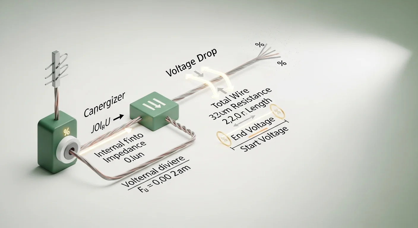
- Voltage Drop: V_drop (V) = I (A) × R (Ω)
- End Voltage: V_end (V) = V_start − V_drop. Clamped to 0 minimum.
Resistance Values Used
- 12 ga Steel: 1.588 Ω / 1,000 ft
- 14 ga Steel: 2.525 Ω / 1,000 ft
- 17 ga Steel: 5.055 Ω / 1,000 ft
- 12 ga Aluminum: 0.988 Ω / 1,000 ft
- 14 ga Aluminum: 1.570 Ω / 1,000 ft
- 17 ga Aluminum: 3.141 Ω / 1,000 ft
Voltage Thresholds (Secret Sauce)
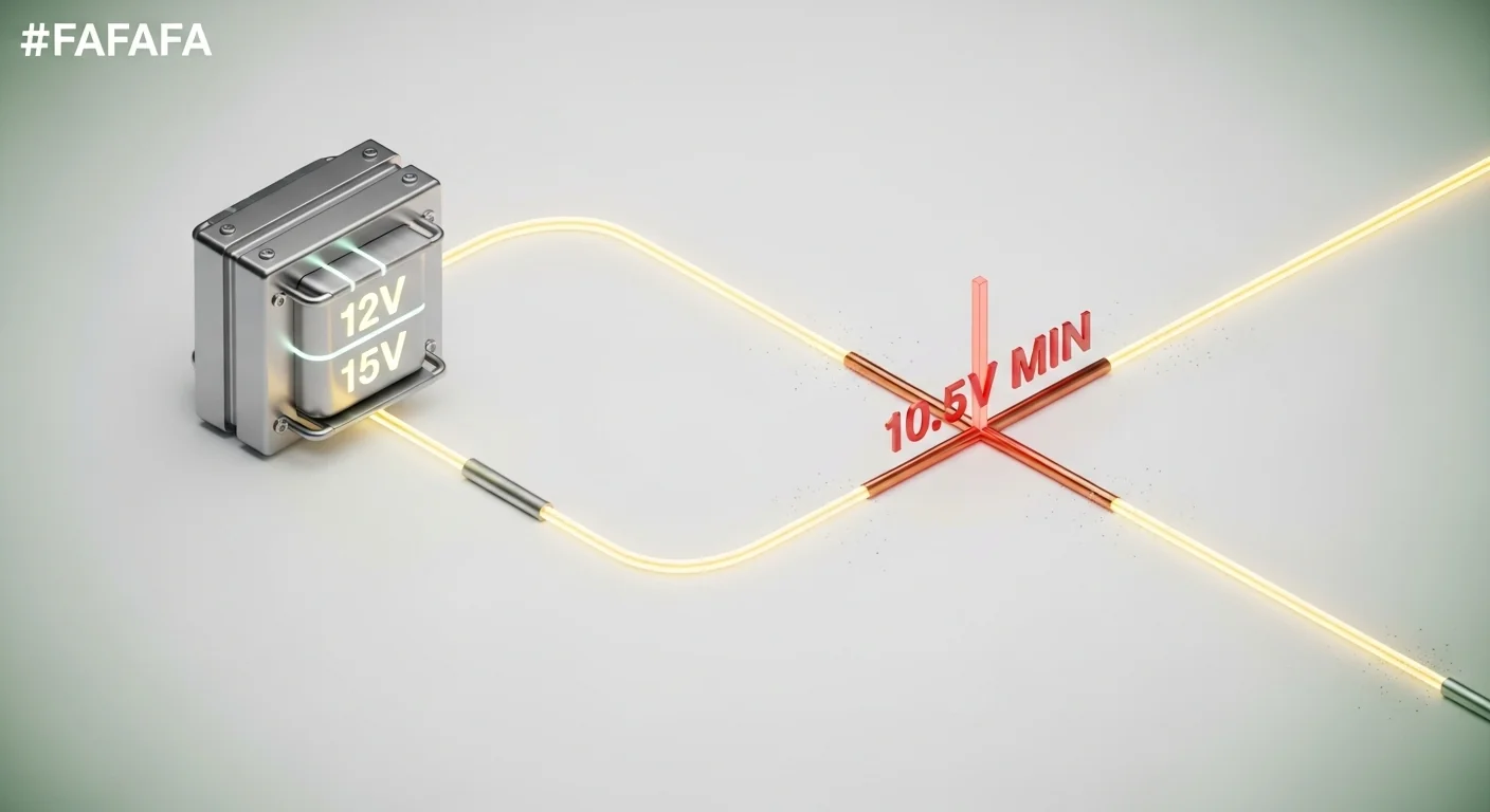
- ≥ 6,000 V → Excellent — effective for cattle, horses, and large animals
- 3,000–5,999 V → Adequate — marginal for large animals; good for sheep & goats
- < 3,000 V → Weak — animals may test and escape the fence
Assumptions & Limits
- Wire resistance is for a single straight run; parallel wires or multiple strands will reduce effective resistance.
- Ground conditions, weed contact, and soil moisture all add leakage resistance not modeled here.
- Pulse current estimate assumes a standard 0.001-second pulse width (industry typical).
- Results are estimates. Always verify with a fence voltmeter at the end of your fence run.
- Voltage cannot drop below 0 V — displayed as 0 V when calculated drop exceeds energizer output.
- Does not account for multiple energizers, fence switchers, or gate gaps.
[put the tool here]
Before running the calculation, have three things ready: the total length of wire you are running (in feet or miles, single-strand), the gauge and material of that wire, and your energizer’s rated output voltage and stored energy from the label or specification sheet. If your fence uses multiple strands, measure the longest single run. For context on how joule ratings affect energizer selection by fence type and animal, the electric fence joule calculator covers that decision separately.
Quick Start (60 Seconds)
- Fence Length: Enter the total single-wire run in feet or select miles from the unit dropdown. One mile equals 5,280 feet. If you are fencing a square 40-acre pasture, the perimeter is roughly 5,280 feet. Do not multiply by number of strands.
- Length Unit: Choose feet for shorter paddocks; miles for large pastures. The calculator converts automatically.
- Wire Gauge and Material: Select the gauge and material that matches your physical wire. If unsure, 12 ga and 14 ga are the most common for permanent cattle and horse fences. 17 ga is typical for temporary or polytape systems using steel.
- Energizer Output Voltage: Use the rated no-load output voltage from your energizer’s label, not the operating voltage. This is usually printed as “Output: X kV” on the unit or in the manual. Enter in volts (so 8 kV = 8000 V). Valid range: 1,000 to 15,000 V.
- Energizer Stored Energy: This is the stored joule rating, not output joules. It is printed on the label. Common values range from 0.25 J for light-duty units to 5 J or more for large pastures. Enter as a decimal (e.g., 2.5).
- Click Calculate: The result shows end-of-fence voltage with a color-coded rating, a calculation breakdown, and a reference table for your wire type.
- Reset: Clears all fields if you want to run a second scenario with different wire or energizer specs.
Inputs and Outputs (What Each Field Means)
| Field | Unit | What It Means | Common Mistake | Safe Entry Guidance |
|---|---|---|---|---|
| Fence Length | ft or mi | Total length of the single wire run from energizer to the far end of the fence | Multiplying perimeter by number of strands, which inflates resistance and underestimates voltage | Measure one strand only. Use a measuring wheel or GPS track for accuracy. |
| Length Unit | ft / mi | Controls how the length input is interpreted before internal conversion to feet | Entering feet but leaving unit on “miles,” making the fence appear 5,280 times longer | Double-check unit selection before calculating. 2,640 ft and 0.5 mi are equivalent. |
| Wire Gauge and Material | AWG / type | Determines the resistance per 1,000 feet used in the calculation | Selecting steel when aluminum was installed, or vice versa. Resistance differs by 60% at the same gauge. | Check wire spool label or test with a multimeter if uncertain. |
| Energizer Output Voltage | Volts (V) | Rated peak output voltage of the energizer under no-load conditions | Using the measured fence voltage instead of the rated output, creating a circular calculation | Read directly from the energizer label or product spec sheet. Range: 1,000 to 15,000 V. |
| Energizer Stored Energy | Joules (J) | Energy stored per pulse, used to estimate the energizer’s effective internal impedance | Confusing stored joules with output joules. The stored rating is always higher and is what should be used. | Look for “Stored Energy” or “Stored Joules” on the label. If only output joules are listed, use a 20% higher estimate. |
| End-of-Fence Voltage (output) | Volts (V) | Estimated voltage at the far terminus of the fence run after resistive drop | Treating this as a guaranteed measurement. It is an estimate assuming no leakage resistance. | Verify with a fence voltmeter at the end of the run. The calculation provides a ceiling, not a measurement. |
| Voltage Drop (output) | Volts (V) | Difference between start voltage and end voltage due to wire resistance | Assuming a small calculated drop means everything is fine. Real fences have additional leakage losses not captured here. | A large calculated drop points to a wire gauge or energizer sizing problem, independent of ground faults. |
Worked Examples (Real Numbers)
Example 1: Half-Mile Cattle Paddock with 12 ga Steel Wire
- Fence Length: 2,640 ft (0.5 mile)
- Wire: 12 ga Steel (1.588 ohms per 1,000 ft)
- Energizer Output Voltage: 8,000 V
- Energizer Stored Energy: 2.0 J
Result: Wire resistance = 4.19 ohms. Estimated internal impedance = 16,000 ohms. Pulse current = 0.500 A. Voltage drop = 2.1 V. End voltage = 7,998 V (Great).
At half a mile with appropriately sized wire and a 2-joule energizer, wire resistance contributes less than 3 volts of drop. The fence voltage at the far end is nearly identical to the energizer’s rated output. Any real-world voltage loss at this fence would be caused by leakage from ground faults, not wire resistance.
Example 2: Two-Mile Perimeter with 14 ga Steel and Underpowered Energizer
- Fence Length: 10,560 ft (2 miles)
- Wire: 14 ga Steel (2.525 ohms per 1,000 ft)
- Energizer Output Voltage: 6,000 V
- Energizer Stored Energy: 1.0 J
Result: Wire resistance = 26.66 ohms. Estimated internal impedance = 18,000 ohms. Pulse current = 0.332 A. Voltage drop = 8.9 V. End voltage = 5,991 V (Adequate).
Even at two miles with 14 ga steel, a 6,000 V / 1-joule energizer delivers adequate but not great voltage. The fence sits just below the 6,000 V threshold for cattle. Any ground fault from a single weed contact could pull this fence into the “Weak” zone. This is the boundary case where upgrading to 12 ga aluminum wire would make a meaningful difference.
Example 3: Ten-Mile Fence with 17 ga Steel and a Light Energizer
- Fence Length: 52,800 ft (10 miles)
- Wire: 17 ga Steel (5.055 ohms per 1,000 ft)
- Energizer Output Voltage: 2,500 V
- Energizer Stored Energy: 0.1 J
Result: Wire resistance = 266.9 ohms. Estimated internal impedance = 31,250 ohms. Pulse current = 0.079 A. Voltage drop = 21.2 V. End voltage = 2,479 V (Weak).
This combination represents an undersized energizer on a very long thin wire. The end voltage falls below 3,000 V, which is insufficient for reliable cattle containment. The wire resistance accounts for part of the drop, but the primary constraint is the low energizer output voltage. No wire gauge improvement alone will fix this scenario; energizer capacity must be increased.
Reference Table (Fast Lookup)
The table below uses a 6,000 V / 1.5 J energizer as the baseline (estimated internal impedance = 12,000 ohms). Values are computed from the resistance formula. Use it to compare wire gauge impact across fence lengths before purchasing wire.
| Length (ft) | Length (mi) | Wire Type | Wire Resistance (ohms) | Voltage Drop (V) | End Voltage (V) | Rating |
|---|---|---|---|---|---|---|
| 2,640 | 0.5 | 12 ga Aluminum | 2.61 | 1.3 | 5,999 | Adequate |
| 2,640 | 0.5 | 12 ga Steel | 4.19 | 2.1 | 5,998 | Adequate |
| 5,280 | 1.0 | 12 ga Steel | 8.38 | 4.2 | 5,996 | Adequate |
| 5,280 | 1.0 | 14 ga Steel | 13.33 | 6.6 | 5,993 | Adequate |
| 10,560 | 2.0 | 12 ga Steel | 16.77 | 8.3 | 5,992 | Adequate |
| 10,560 | 2.0 | 17 ga Steel | 53.38 | 26.3 | 5,974 | Adequate |
| 26,400 | 5.0 | 12 ga Aluminum | 26.09 | 12.9 | 5,987 | Adequate |
| 26,400 | 5.0 | 14 ga Steel | 66.66 | 32.7 | 5,967 | Adequate |
| 52,800 | 10.0 | 12 ga Steel | 83.84 | 41.3 | 5,959 | Adequate |
| 52,800 | 10.0 | 17 ga Steel | 266.9 | 127.8 | 5,872 | Adequate |
Notice that wire resistance alone rarely drives the fence below threshold when the energizer is appropriately sized. The table confirms that gauge selection matters most at long distances with light energizers. At these values (6,000 V / 1.5 J baseline), switching from 17 ga steel to 12 ga aluminum on a 10-mile run saves roughly 86 volts of wire-resistance drop.
How the Calculation Works (Formula + Assumptions)

Show the calculation steps
Step 1 – Wire Resistance:
R_wire (ohms) = Fence Length (ft) x [Resistance per 1,000 ft for selected gauge] / 1,000
Example: 10,000 ft of 14 ga steel = 10,000 x 2.525 / 1,000 = 25.25 ohms
Step 2 – Energizer Internal Impedance Estimate:
R_int (ohms) = (V_start^2 x 0.0005) / Joules
Minimum clamp: R_int cannot fall below 50 ohms.
This derives the effective impedance that opposes current flow from the stored energy and voltage rating. A 2.0 J energizer at 8,000 V produces R_int = (64,000,000 x 0.0005) / 2.0 = 16,000 ohms.
Step 3 – Peak Pulse Current:
I (amps) = V_start / (R_int + R_wire)
This is the estimated peak current during the discharge pulse through the total circuit impedance.
Step 4 – Voltage Drop:
V_drop (V) = I x R_wire
This is the resistive loss across the wire during the pulse.
Step 5 – End-of-Fence Voltage:
V_end (V) = V_start – V_drop, minimum 0 V
Rounded to the nearest whole volt for display.
Rounding: All intermediate values use full floating-point precision. Only the final displayed voltage is rounded to the nearest integer.
Unit conversion: If miles are selected, the calculator multiplies by 5,280 before applying the resistance formula.
Assumptions and Limits
- The model assumes a single-strand wire run with uniform resistance. Parallel strands, spliced wires, or mixed gauges on the same run are not modeled.
- Leakage resistance from ground faults (vegetation, wet insulators, soil contact) is not included. Real-world end voltage will typically be lower than calculated when any leakage path exists.
- The internal impedance model is derived from the energizer’s energy storage and rated voltage using a simplified discharge model. Actual energizer circuitry varies by manufacturer and design.
- Pulse width is treated as 0.001 seconds (1 millisecond), which is typical for most commercial electric fence energizers. Units with shorter or longer pulse widths will produce slightly different results.
- Wire temperature effects are not modeled. Steel resistance increases approximately 0.4% per degree Celsius above 20 C; aluminum increases approximately 0.4% per degree Celsius. For extreme temperature ranges, actual resistance may differ from the values used.
- The calculator does not account for gate gaps, fence switches, grounding system resistance, or multi-energizer configurations. Each of these can significantly affect real-world performance.
- Results are most accurate when energizer specifications come from manufacturer data, not from measured fence voltages, which already include all loss factors.
Standards, Safety Checks, and Warnings
Critical Warnings
- Under 3,000 V: Livestock will test and escape. At voltages below 3,000 V, most cattle and horses do not receive a strong enough shock to condition avoidance behavior. Animals that have been shocked at low voltage once often learn to push through the fence. Reaching this condition is a containment failure, not just a performance issue.
- Vegetation contact is the primary real-world cause of low fence voltage. A single weed or grass stem touching the wire can bleed thousands of volts to ground. This calculator does not model that loss. If a fence tests well in winter but fails in summer, vegetation contact is the first thing to check. This is not a wiring or energizer problem.
- The calculated end voltage is a best-case ceiling, not a guaranteed measurement. Any ground fault, corroded connection, or insulator failure will reduce actual voltage below the calculated value. Treat the result as what the fence should deliver if everything is in perfect condition.
- Energizer output voltage is not the same as fence operating voltage. The rated output is a no-load value. Under load (fence connected), voltage will be lower. This calculator uses the no-load rating as the starting point, which means real-world end voltage will typically be lower still.
Minimum Standards
- For cattle and horses: 6,000 V minimum at the far end of the fence. Below this, the fence is marginal and vulnerable to failure under wet conditions or vegetation pressure.
- For sheep, goats, and pigs: 4,000 V minimum. These species often have thicker coats or lower body contact with the wire; higher voltage compensates for reduced conductivity.
- For predator exclusion (coyotes, dogs): 5,000 V or higher. Predators test fences repeatedly and at different points; a uniform, high voltage across the entire run is more effective than a strong reading near the energizer.
- Wire resistance for a permanent cattle fence should not exceed 100 ohms total. If your calculation shows resistance above this threshold, consider splitting the fence into shorter runs with a second energizer lead, or upgrading to lower-resistance wire.
Competitor trap: Most voltage drop guides for electric fences focus only on wire resistance and ignore the energizer’s effective output impedance. That produces unrealistically large voltage drop estimates because they treat the energizer as a fixed-voltage source rather than a source with internal impedance. The actual voltage drop across fence wire at normal fence lengths is small compared to the energizer’s own internal voltage regulation. When a fence is reading 2,000 V at the end and 7,000 V at the energizer, the cause is almost never the wire itself. It is a low-impedance ground fault draining current before the voltage can propagate. Knowing this distinction changes where you look when you go to troubleshoot.
For fences that combine electric wire with physical barriers, the H-brace fence calculator can help verify that corner and brace post configurations maintain structural tension that keeps wire off the ground and away from leakage contact points.
Woven wire fences used as a base layer under electric fence systems change the grounding dynamics entirely. The woven wire fence calculator can help size that layer correctly before adding the electric wire on top.
Common Mistakes and Fixes
Mistake: Measuring Voltage at the Energizer and Concluding the Fence Is Fine
A voltmeter reading of 7,500 V at the energizer terminal tells you the energizer is working. It tells you nothing about what is happening 2 miles away. Ground faults and vegetation contact can drop voltage to near zero within a few hundred feet without affecting the near-end reading at all. Fix: Always test voltage at the far end of the fence run and at any trouble spots such as corners, gates, and low points where vegetation is likely to contact the wire.
Mistake: Using 17-Gauge Wire on Permanent Long Runs
17-gauge wire is appropriate for temporary fencing and short paddock divisions. At 5.055 ohms per 1,000 feet, a 5-mile run adds 133 ohms of wire resistance. While the calculator shows this still produces acceptable voltage drop in isolation, 17-gauge steel is also more susceptible to mechanical failure, corrosion, and sagging over time, creating additional resistance at joints and contact points. Fix: Use 12 or 14-gauge steel, or 12-gauge aluminum, for permanent fence runs longer than one mile.
Mistake: Confusing Stored Joules with Output Joules
Many energizers label both values. Stored joules represent the energy drawn from the power source and stored in the capacitor before each pulse; output joules represent the energy actually delivered to the fence. Stored joules are always the higher number. Entering output joules when stored joules are required overestimates the energizer’s internal impedance in this model, which makes the calculated voltage drop appear larger than it actually is. Fix: Look specifically for “Stored Energy (J)” on the label. If only output joules are listed, the stored value is typically 20 to 30% higher.
Mistake: Not Accounting for Multiple Return Paths on Multi-Strand Fences
Multi-strand fences often use alternating hot and ground wires. In this configuration, the fence wire length for the purpose of resistance calculation is only the hot wire run, not the total of all strands. Entering total wire length inflates the calculated resistance and produces a pessimistic voltage estimate. Fix: Enter only the length of the single hot wire run in the calculator. If all strands are hot (connected to the same terminal), the parallel configuration actually reduces effective resistance below the single-wire calculation.
Mistake: Ignoring Seasonal Variation in Voltage Readings
A fence that reads 6,500 V in January can read 3,000 V in July from the same energizer with no changes to the wire. The cause is vegetation growing into contact with the wire during the growing season, which dramatically increases leakage current. Fence managers who calculate once and never re-test miss this entirely. Fix: Test fence voltage at the far end at least monthly during the growing season. The pasture weed management calculator can help plan vegetation control programs that reduce seasonal voltage loss.
Next Steps in Your Workflow
After running the voltage drop calculation, the most useful next action is to verify it with a physical fence voltmeter at the far end of the run. If the measured voltage is significantly lower than the calculated estimate, the difference represents energy being lost to leakage paths that the calculation does not model. Walk the fence line from the low-reading point back toward the energizer, testing every 500 feet, until you find where the voltage recovers. The section where it drops sharply is where the ground fault or vegetation contact is located. Proper pasture rotation scheduling also affects fence performance: the rotational grazing calculator can help design paddock sequences that reduce the time any single section is under heavy vegetation pressure from livestock trampling and grazing near the wire.
If the calculation shows that your energizer output voltage is simply too low to deliver adequate end-of-fence voltage regardless of wire gauge choice, the sizing decision moves to joule capacity. Energizer selection should account for total fence length, wire resistance, and the animal species being contained. Livestock water system planning is often scheduled at the same time as fence infrastructure upgrades; the cattle water requirement calculator can run that side of the project in parallel. For corner and brace post infrastructure that will anchor a new wire run, the fence tension and temperature calculator can predict how wire tension changes seasonally and inform proper initial tensioning.
FAQ
What is the minimum voltage needed for an electric fence to work on cattle?
For reliable cattle containment, the fence should deliver at least 6,000 V at the far end of the run under normal conditions. Cattle can receive a deterrent shock at lower voltages, but conditioning is much weaker. Fences reading consistently below 4,000 V at the end point will be tested repeatedly by cattle, especially young stock. The 6,000 V threshold assumes standard fur coat contact; wet conditions require higher voltage to compensate for reduced skin resistance.
Does wire gauge make a big difference in electric fence voltage?
For typical fence lengths under 5 miles with an appropriately sized energizer, wire gauge alone rarely causes voltage failure. The voltage drop from wire resistance is small compared to the energizer’s rated output for most practical configurations. Wire gauge matters more for long runs, light energizers, or scenarios where the fence must perform within a narrow voltage band. Gauge also affects mechanical durability and corrosion resistance, which indirectly affects voltage through joint quality over time.
Why is aluminum wire often recommended over steel for electric fences?
Aluminum has significantly lower electrical resistance than steel at the same gauge. 12-gauge aluminum wire has a resistance of 0.988 ohms per 1,000 feet versus 1.588 ohms for 12-gauge steel, a 38% reduction. Aluminum also does not rust, which keeps joint resistance low over the life of the fence. The trade-off is lower tensile strength; aluminum breaks more easily under mechanical stress from deer impact or tree falls, and it cannot be spliced with the same tension as high-tensile steel.
What causes low electric fence voltage if the wire resistance calculation looks fine?
Wire resistance accounts for only one source of voltage loss. Real-world low voltage on an otherwise properly sized system is almost always caused by leakage resistance, meaning current escaping to ground somewhere along the fence. Common causes include vegetation contact with the wire, wet or cracked insulators, wire touching a metal post, a gate handle or spring that is grounding the hot wire, or a corroded connection at a splice or tensioner adding significant resistance in series with the circuit.
How do stored joules relate to the voltage a fence delivers?
Stored joules represent the energy available to drive a pulse through the fence circuit. A higher joule rating means the energizer can drive more current through higher-resistance loads before the pulse voltage collapses. For a clean, low-resistance fence, a low joule rating still delivers high voltage because the load is small. For a long fence with many leakage paths, a higher joule rating maintains voltage under load. Joules and volts are related through the circuit impedance; neither spec alone tells the full story.
Can this calculator be used for poultry or small animal fencing?
The voltage thresholds used in the calculator (6,000 V great, 3,000 V adequate, below 3,000 V weak) are calibrated for cattle and large livestock. Poultry netting, rabbit fencing, and small animal systems typically operate at lower voltages and with net-style conductors that have very different resistance characteristics. The formula for voltage drop still applies, but the threshold interpretation shown in the color-coded results does not directly translate to poultry applications where 2,000 to 4,000 V is often the target range.
Conclusion
Wire resistance is a predictable, calculable factor in electric fence performance. Running these numbers before installing a fence or before buying a new energizer avoids the most expensive kind of mistake: discovering that the energizer was fine all along and the real problem was a corroded splice 3 miles out from the barn. The calculation shows what the fence should deliver if everything is clean and intact. The gap between the calculation and a real voltmeter reading tells you exactly how much energy is leaking to ground, and that is the number worth troubleshooting.
The single most important mistake to avoid is reading voltage at the energizer and concluding the fence is functional. That reading only tests the energizer. The only test that matters for containment is at the far end of the fence, with all gate handles connected and all strands in their normal operating position. For building out the broader pasture infrastructure around a well-functioning fence system, the pasture stocking rate calculator can help match animal pressure to land capacity once containment is confirmed reliable.
Lead Data Architect
Umer Hayiat
Founder & Lead Data Architect at TheYieldGrid. I bridge the gap between complex agronomic data and practical growing, transforming verified agricultural science into accessible, mathematically precise tools and guides for serious growers.
View all tools & guides by Umer Hayiat →