The slope angle at which a tractor statically tips and the slope angle at which it actually rolls over in the field are two different numbers. Most landowners and small-scale operators work only with the first figure, which consistently leads to serious incidents on terrain that, by the math, appeared safe. The static tipping angle describes the geometric tipping point of a rigid, stationary machine on a smooth, uniform incline. Real terrain, real implements, and real operating conditions make that number optimistic by a meaningful margin.
This tractor side slope limit calculator computes the static tipping angle from your specific track width and center of gravity height, applies a 10-degree dynamic penalty to account for terrain-induced CG shifts, and flags the point at which your planned operating slope exceeds the adjusted safe threshold. It also applies a raised-loader CG correction when applicable. What this tool does not do: it does not model tire flex, wet-ground friction loss, combined fore-aft and lateral tilt, or operator reaction time. It is a physics-based screening tool, not a substitute for a farm safety audit or manufacturer operating guidelines.
Bottom line: After running the calculator, you will know whether your slope, track width, CG height, and implement combination falls inside the dynamic safe zone, inside the caution zone, or beyond the rollover threshold. That result should directly inform whether you operate, widen your track, lower your implement, or choose a different mowing direction.
Use the Tool
| Track Width | CG Height | Static Tip° | Dynamic Limit° | Risk Level |
|---|
How This Calculator Works
This tractor side-slope limit calculator uses industry-standard statics math combined with real-world dynamic corrections drawn from OSHA agricultural guidelines and tractor stability research.
e.g. arctan(72÷2 ÷ 33) = arctan(1.09) ≈ 47.5°
Raising a loader shifts weight high and forward, reducing safe angle significantly.
Bumps, holes, turns, and momentum all reduce the effective safe angle. 10° is a conservative real-world margin.
The “Centrifugal Roll”: even if the slope is below the static threshold, a tire dropping into a hole violently shifts CG outward. This is the most common fatal scenario.
Assumptions & Limitations: This calculator uses simplified point-mass statics. It does not account for: tire flex and deformation, wet/slippery ground conditions, speed of travel, side-slope combined with fore-aft tilt, uneven ballasting, or tire pressure variation. Always validate with a qualified farm safety professional. Never operate on slopes approaching the calculated limits.
[put the tool here]
Before entering values, have the following ready: your tractor’s outside-to-outside tire measurement in inches (not the axle center-to-center distance), an estimated or manufacturer-listed center of gravity height from ground level, and the steepest angle in degrees of the slope you intend to cross. If you do not have the CG height from documentation, a value between 30 and 36 inches is a reasonable baseline for compact utility tractors without ballast. Select your implement type carefully, particularly if you are operating with a front-end loader, since the raised-bucket option triggers the 15-inch CG height adjustment built into the calculation logic. For slope measurement, a digital inclinometer held at the tractor’s frame level gives a more accurate reading than visual estimation. If you are planning fencing work on sloped terrain, the H-brace fence calculator covers post and brace sizing for angled fence runs where tractor access will be needed.
Quick Start (60 Seconds)
- Track Width (inches): Measure outside tire edge to outside tire edge on the same axle. Do not use the rim width or the axle width. This number is the full footprint of the tractor on the ground. Acceptable range: 36 to 144 inches.
- Center of Gravity Height (inches): Check your tractor’s operator manual for CG data, or use 30 to 36 inches for a typical compact tractor without ballast. Rear ballast lowers CG; a full fuel tank or heavy loader frame raises it. Enter the baseline height before implement corrections.
- Implement Type: Select the implement currently attached. If your front loader bucket is in the raised working position, select “Front loader (bucket raised)” specifically. This is not the same as a lowered transport position and has a significant effect on the result.
- Slope Angle (degrees): Enter the steepest cross-slope angle you plan to traverse, not the average slope. A 10-degree slope is approximately an 18 percent grade. A 15-degree slope is approximately 27 percent grade. Use degrees, not percent grade, in this field.
- Run the calculation: Click “Calculate Slope Safety.” Results will not appear until all four fields are valid. If an error appears next to a field, correct that field before the calculation will proceed.
- Read the dynamic limit, not just the static angle: The large number displayed is the static tipping angle. The number that determines your safe operating ceiling is the dynamic limit, which is 10 degrees lower. Your planned slope is evaluated against the dynamic limit.
- Check the traffic light and warning box: Green means your slope is inside the dynamic margin. Orange means you are within 5 degrees of the limit. Red means your slope exceeds the dynamic rollover threshold and operation at that angle is not recommended.
Inputs and Outputs (What Each Field Means)
| Field Name | Unit | What It Measures | Common Mistake | Safe Entry Guidance |
|---|---|---|---|---|
| Track Width | Inches | The horizontal distance between the outer edges of the tires on the same axle. This is the lever arm that resists tipping. | Using axle center-to-center distance instead of outside-to-outside tire measurement. This underestimates track width and makes the result artificially unsafe. | Measure physically with a tape on flat ground. Use the rear axle measurement for most two-wheel-drive tractors. Enter between 36 and 144 inches. |
| CG Height | Inches | The vertical distance from the ground to the tractor’s center of gravity. Controls how far the CG must shift laterally before reaching the tipping line. | Using the seat height or hood height as a proxy for CG. The CG is typically well below the seat, usually between 28 and 40 inches for compact tractors. | Check the operator manual. If unavailable, 33 inches is a conservative default for a compact tractor. Add rear ballast data if you know the tractor is heavily weighted at the rear. |
| Implement Type | Category (dropdown) | Determines whether a 15-inch CG penalty is applied. Only the raised loader position triggers the correction in this calculator. | Selecting “loader lowered” when the bucket will actually be raised during operation. Mowing with a raised loader is one of the highest-risk tractor configurations. | Select the implement state that reflects actual working position, not transport position. If you lower the loader to mow, select the lowered option. |
| Slope Angle | Degrees | The cross-slope angle of the terrain you plan to traverse with the tractor. | Entering percent grade instead of degrees. A 20 percent grade equals approximately 11.3 degrees, not 20 degrees. These are not interchangeable. | Measure with a digital inclinometer or clinometer app at the steepest point of the actual traverse, not at a representative average location. |
| Static Tipping Angle (output) | Degrees | The theoretical slope at which a stationary tractor on a perfectly smooth surface would begin to tip. This is the geometric ceiling, not the operational ceiling. | Treating this as the safe operating slope. The dynamic limit, which is 10 degrees lower, is the number to use for operational decisions. | Use as a baseline comparison value only. The dynamic limit is the operative threshold. |
| Dynamic Rollover Limit (output) | Degrees | The adjusted safe operating ceiling after the 10-degree dynamic penalty is applied. This is the number your planned slope is evaluated against. | Ignoring this number and only looking at the static angle, which leads to operating dangerously close to or beyond the real rollover threshold. | Your planned slope must be below this number. Ideally, maintain at least a 5-degree margin below the dynamic limit. |
| Risk Level (output) | Safe / Caution / Danger | A traffic-light classification comparing your slope to the dynamic limit. Caution is triggered when the slope is within 5 degrees of the dynamic limit. | Treating “Caution” as an acceptable operating state. The caution zone means a single terrain irregularity can push the tractor past the tipping point. | Target Safe status. If the result is Caution, widen track width, lower any raised implement, or select a different operating direction before proceeding. |
Worked Examples (Real Numbers)
Example 1: Standard Compact Tractor, No Implement, Gentle Cross-Slope
- Track Width: 72 inches
- CG Height: 33 inches
- Implement: No implement / standard configuration
- Planned Slope: 15 degrees
Calculation: Static Tipping Angle = arctan(72 / 2 / 33) = arctan(1.091) = 47.5 degrees. Dynamic Limit = 47.5 – 10 = 37.5 degrees.
Result: SAFE. The 15-degree planned slope is 22.5 degrees below the dynamic rollover limit of 37.5 degrees.
A 72-inch track width is one of the most forgiving common configurations. At 15 degrees, this tractor retains a substantial safety margin even accounting for terrain irregularities and dynamic CG shift. Mowing speed and ground condition remain independent risk factors not captured by this calculation.
Example 2: Front Loader Raised, Narrower Track, Moderate Slope
- Track Width: 60 inches
- CG Height: 34 inches (baseline, before loader correction)
- Implement: Front loader, bucket raised (working position)
- Planned Slope: 18 degrees
Calculation: Effective CG Height = 34 + 15 = 49 inches (raised-loader penalty applied). Static Tipping Angle = arctan(30 / 49) = arctan(0.612) = 31.5 degrees. Dynamic Limit = 31.5 – 10 = 21.5 degrees.
Result: CAUTION. The 18-degree planned slope is within 3.5 degrees of the 21.5-degree dynamic limit.
This is the configuration responsible for a large share of tractor rollovers. A 34-inch CG with the loader lowered yields a static angle of 41.5 degrees and a dynamic limit of 31.5 degrees. Raising the bucket collapses that margin severely. At 18 degrees with 3.5 degrees of clearance, a single tire drop of 4 to 6 inches can exceed the threshold instantly.
Example 3: Narrow Track, Steep Slope, No Implement
- Track Width: 48 inches
- CG Height: 36 inches
- Implement: No implement / standard configuration
- Planned Slope: 22 degrees
Calculation: Static Tipping Angle = arctan(24 / 36) = arctan(0.667) = 33.7 degrees. Dynamic Limit = 33.7 – 10 = 23.7 degrees.
Result: CAUTION. The 22-degree planned slope is within 1.7 degrees of the 23.7-degree dynamic limit.
A 48-inch track on a 36-inch CG tractor at 22 degrees has almost no remaining margin. This configuration is one unexpected ground hole away from a rollover. Adding 4-inch billet wheel spacers per side (increasing track width to 56 inches) would raise the static angle to 37.0 degrees and the dynamic limit to 27.0 degrees, restoring a 5-degree margin at this same slope.
Reference Table (Fast Lookup)
All values computed using the formula: Static Tipping Angle = arctan(Track Width / 2 / Effective CG Height). Dynamic Limit = Static Angle minus 10 degrees. Loader-raised rows use Effective CG = Baseline CG + 15 inches.
| Track Width (in) | Baseline CG (in) | Implement State | Effective CG (in) | Static Tip Angle | Dynamic Limit | Max Safe Slope Class |
|---|---|---|---|---|---|---|
| 48 | 30 | None | 30 | 38.7° | 28.7° | Moderate slopes (<25°) |
| 48 | 36 | Loader raised | 51 | 25.2° | 15.2° | Gentle slopes only (<12°) |
| 60 | 33 | None | 33 | 42.3° | 32.3° | Moderate-steep (<28°) |
| 60 | 34 | Loader raised | 49 | 31.5° | 21.5° | Gentle slopes only (<17°) |
| 72 | 33 | None | 33 | 47.5° | 37.5° | Steep (<32°) |
| 72 | 36 | Loader raised | 51 | 35.2° | 25.2° | Moderate (<20°) |
| 84 | 33 | None | 33 | 51.9° | 41.9° | Steep (<36°) |
| 84 | 36 | Loader raised | 51 | 38.7° | 28.7° | Moderate-steep (<23°) |
| 96 | 33 | None | 33 | 55.4° | 45.4° | Very steep (<40°) |
| 96 | 36 | Loader raised | 51 | 43.0° | 33.0° | Steep (<28°) |
How the Calculation Works (Formula and Assumptions)
Show the calculation steps
Step 1: Determine effective CG height. If the implement type is “Front loader (bucket raised),” add 15 inches to the entered CG height. This correction reflects the physical shift of weight mass upward and forward when the loader is in the working position. All other implement selections use the entered CG height without adjustment.
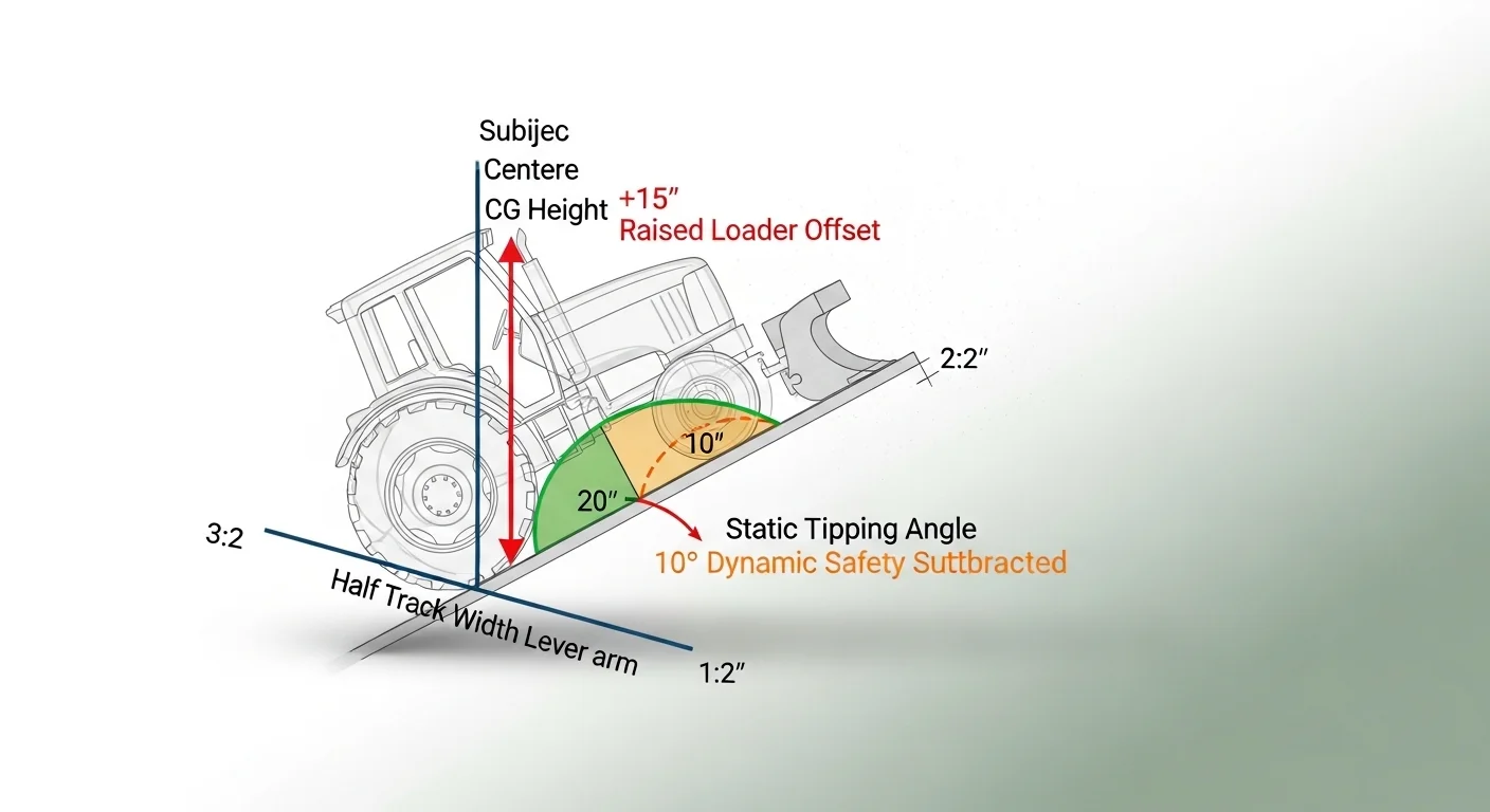
Step 2: Compute the static tipping angle. The formula is: Static Tipping Angle (degrees) = arctan( (Track Width / 2) / Effective CG Height ). The half-track width represents the horizontal distance from the tractor’s centerline to the downhill tire contact point. The effective CG height is the vertical distance from the ground to the CG. The ratio of these two values is the tangent of the angle at which the CG is directly above the downhill tire, which is the geometric tipping point. Results are rounded to one decimal place in degrees.
Step 3: Apply the dynamic penalty. Subtract 10 degrees from the static tipping angle to produce the Dynamic Rollover Limit. This 10-degree margin accounts for kinetic energy effects during terrain contact events (holes, ruts, ridges), momentum during directional changes, and the non-uniform surface conditions present in actual field operation. This is a conservative fixed offset, not a percentage.
Step 4: Evaluate the planned slope. The planned slope (in degrees) entered by the user is compared directly to the dynamic limit. If the slope is greater than the dynamic limit, the result is Danger. If the slope is within 5 degrees of the dynamic limit, the result is Caution. Otherwise, the result is Safe.
Rounding rule: Intermediate calculations use full floating-point precision. The final static and dynamic angles are displayed rounded to one decimal degree. The risk classification uses unrounded values internally.
Unit convention: All angles are in degrees throughout. Percent grade can be converted to degrees using: Degrees = arctan(Grade / 100). A 20 percent grade equals approximately 11.3 degrees, not 20 degrees.
Assumptions and Limits
- The formula models the tractor as a rigid body with a fixed point-mass CG. In reality, CG shifts dynamically as implements move, fuel burns, and ballast loads change.
- The 15-inch CG correction for a raised loader is a conservative estimate. Actual CG shift depends on loader arm length, bucket load weight, and bucket geometry. A heavily loaded bucket may shift the CG more than 15 inches.
- The 10-degree dynamic penalty is a fixed engineering margin. It does not scale with slope steepness, travel speed, or ground softness. On wet, loose, or compacted soil with low friction, the actual safe operating angle may be significantly lower.
- The calculation does not account for combined fore-aft slope and lateral slope occurring simultaneously. Both tilts acting at the same time reduce the effective safe angle further than either in isolation.
- Tire flex, sidewall deformation, and differential tire pressure can effectively shift the contact point of the downhill tire, reducing the functional track width below the measured value.
- The formula assumes the slope is uniform and continuous across the full traverse. A localized depression or mound at any point along the path can instantaneously create a greater effective slope than the average terrain angle.
- This calculator does not account for operator behavior, travel speed, or the dynamics of cornering or turning on slopes, all of which substantially affect actual rollover risk.
Standards, Safety Checks, and Secret Sauce Warnings
Critical Warnings
- The second-pass rollover trap. A first mowing or working pass across a slope often proceeds without incident. The tractor flattens grass, creates wheel ruts, and can disturb or expose ground openings such as animal burrows. On the second pass, especially in the same tracks, a downhill tire can drop into a rut or hole created during the first pass. The sudden downhill drop violently shifts the kinetic energy of the machine outward, moving the CG beyond the tipping point almost instantaneously. There is generally no time for steering or braking correction. This mechanism operates even when the static slope angle is comfortably below the calculated static tipping angle.
- The static-to-dynamic gap is not optional. Operating at or near the static tipping angle without the dynamic margin is not a calculated risk. It is a condition in which a single terrain irregularity, a steering correction, or a mild slope variation can cause rollover. The 10-degree subtraction in this calculator represents the minimum, not the ideal, safety buffer. Field conditions frequently justify a larger margin.
- Raised implement risk amplification. A raised front-end loader is not simply a different implement mode. It restructures the machine’s entire stability envelope. At 48-inch track width with a 36-inch CG, raising the loader collapses the dynamic limit from 28.7 degrees to 15.2 degrees. Operators who switch between lowered and raised positions during a single pass without re-assessing slope risk are introducing a variable not captured in any single calculation snapshot.
- Inclinometer at frame level, not operator estimate. Slope estimation by eye is systematically inaccurate. Slopes consistently appear shallower visually than they measure physically, particularly when the operator is already positioned on the slope. A magnetic digital inclinometer attached to the tractor frame provides a real-time reading that eliminates visual estimation error entirely.
Minimum Standards
- ROPS must be present and in the upright locked position on all tractors operated on slopes. Folded or absent ROPS remove the protected crush zone that the seatbelt is designed to keep the operator within during a rollover.
- A seatbelt or four-point harness must be worn at all times when operating with ROPS. An unrestrained operator can be thrown from the ROPS zone during rollover, which is the primary cause of ROPS-equipped tractor fatalities.
- The dynamic limit produced by this calculator should be treated as a maximum boundary, not a target. A conservative operational target of 5 degrees below the dynamic limit provides additional margin for unmeasured terrain variation.
- Track width adjustments using wheel spacers should be evaluated for their effect on bearing load and wheel hub torque before installation. Manufacturer specifications for maximum offset should be consulted.
Competitor trap: Most online tractor rollover resources publish a single number as “the safe slope for a tractor,” typically 20 or 25 degrees, without reference to track width, CG height, or implement state. That approach is not slope safety guidance. It is slope mythology. A 48-inch-track tractor with a raised loader has a dynamic rollover limit that can fall below 15 degrees. A 96-inch-track tractor without an implement has a dynamic limit above 45 degrees. Publishing a universal slope threshold as if tractor geometry does not exist produces false confidence in the most vulnerable configurations. This calculator is designed specifically to replace that oversimplification with machine-specific values. For pasture work that may affect how you plan terrain use across your property, the pasture stocking rate calculator can help you evaluate land use decisions that reduce how often heavy equipment needs to cross steep terrain at all.
If you need to run electric fencing on or near sloped terrain where tractor access determines post placement, the woven wire fence calculator covers material quantities for fence runs on varied terrain profiles.
Common Mistakes and Fixes
Mistake: Using Percent Grade Instead of Degrees
Percent grade and degrees are related by a nonlinear function: arctan(grade / 100) = degrees. A 20 percent grade is 11.3 degrees, not 20 degrees. Entering percent grade into the degree field produces a result that dramatically understates the actual slope angle, making a steep slope appear safe. This error is especially consequential on slopes above 15 percent grade where the gap between the two units grows faster.
Fix: Measure the slope angle directly with a digital inclinometer, or convert percent grade to degrees using arctan(grade / 100) before entering the value.
Mistake: Measuring Axle Width Instead of Outside Tire Width
The resistance to lateral tipping is provided by the full contact footprint of the tires on the ground, not the axle center-to-center distance. Using the narrower axle measurement underestimates track width, which in turn makes the calculated static angle appear smaller than the actual geometric limit. This produces an artificially conservative result rather than an accurate one. It is a directionally safe error, but it leads to unnecessary restrictions on terrain that is actually within the machine’s physical envelope.
Fix: Measure from the outer edge of the left tire sidewall to the outer edge of the right tire sidewall on the same axle while the tractor is on flat ground.
Mistake: Selecting Loader Type Based on Starting Position, Not Working Position
Operators who begin a task with the loader lowered but raise it repeatedly during the work cycle are operating at the higher CG height for significant portions of the traverse. Selecting “loader lowered” in the calculator under these conditions bypasses the 15-inch CG correction and produces a dynamic limit that does not reflect the actual machine state during working passes. This is a systematic underestimation of risk on any slope where the loader is raised during forward movement.
Fix: Select “Front loader (bucket raised)” if the bucket will be raised at any point while crossing or traversing a slope. Use the worst-case implement position for the slope safety calculation.
Mistake: Ignoring Ground Condition When Operating Near the Caution Zone
The 10-degree dynamic penalty in this calculator assumes terrain irregularities consistent with maintained pasture or field conditions. Soft, saturated, or heavily rutted ground changes the effective contact geometry by allowing the downhill tire to sink further than the uphill tire, functionally increasing the slope angle experienced by the machine even when the terrain angle is unchanged. The calculator has no input for ground softness, so operators working in wet conditions near the caution boundary are operating with less actual margin than the result displays.
Fix: In wet or soft conditions, add an additional 5-degree mental safety buffer beyond the dynamic limit displayed. Reschedule slope operations after at least 48 hours of dry weather when soil bearing strength has recovered. If managing heavy equipment near livestock water infrastructure, the stock tank algae calculator and related water management tools on The Yield Grid address the terrain planning that affects where equipment regularly needs to travel.
Mistake: Treating the First Pass as a Stability Validation
Completing one pass across a slope without incident does not confirm that the slope is within the machine’s safe operating envelope. The first pass can create or expose ground conditions that make subsequent passes more dangerous: wheel ruts that channel the downhill tire, grass flattened in a direction that reduces friction, or disturbed soil that opens previously concealed animal burrows. The first pass surviving is not a safety clearance for the second pass at the same angle.
Fix: Re-evaluate the slope using the calculator before each new field operation session, particularly if conditions have changed since the previous visit. Physically inspect the traverse path for new openings, ruts, or soil disturbance before each pass in a multi-pass operation.
Next Steps in Your Workflow
Once you have a specific dynamic limit from this tractor side slope limit calculator, the most direct structural intervention is track width adjustment. Adding billet wheel spacers to both sides of the rear axle widens the footprint without altering implement configuration or mowing approach. The table in the reference section shows how much the dynamic limit improves with each track width increment, and for many narrow-track machines operating between 15 and 25 degrees, a moderate track width increase moves the result from Caution to Safe with meaningful margin. Before purchasing spacers, verify the manufacturer’s maximum allowable axle offset and the bearing load rating at the extended position.
If track width adjustment is not feasible, the second most impactful change is operating direction. Traversing a slope laterally is more risky than operating up and down the slope for the same terrain, because lateral traversal exposes the machine to the full tipping moment. Where the slope permits it, switching from across-slope passes to up-and-down passes dramatically reduces lateral CG exposure, even if it creates other challenges like fuel delivery angles or implement efficiency. For larger property planning that involves both slope management and fencing decisions where tractors repeatedly work near steep terrain, the electric fence calculator can assist in planning perimeter and paddock layouts that minimize high-risk tractor travel paths while accounting for livestock containment requirements.
FAQ
What is the maximum safe side slope for a tractor?
There is no single universal answer. The safe side slope depends on track width, center of gravity height, implement type, and ground condition. This calculator computes the specific dynamic rollover limit for your machine configuration. A narrow-track tractor with a raised loader may have a safe operating ceiling below 15 degrees, while a wide-track machine without an implement may safely traverse slopes above 35 degrees.
How does a raised front-end loader affect rollover risk?
Raising a front-end loader shifts the machine’s center of gravity upward and forward, effectively increasing CG height. This calculator applies a 15-inch CG height addition for the raised loader position. The increase in CG height reduces the static tipping angle and the dynamic rollover limit, sometimes collapsing the safe operating range by 10 to 15 degrees compared to the same tractor with the loader lowered or absent.
What is the difference between static tipping angle and dynamic rollover limit?
The static tipping angle is the theoretical angle at which a motionless tractor on a perfectly smooth slope would tip. The dynamic rollover limit subtracts 10 degrees from that value to account for the kinetic energy effects of terrain irregularities, holes, ruts, and directional changes during actual field operation. The dynamic limit is the operative number for making go or no-go decisions.
Can I use percent grade instead of degrees in this calculator?
No. The slope angle field requires degrees. Percent grade and degrees are not interchangeable. To convert percent grade to degrees, take the arctangent of the grade divided by 100. A 20 percent grade equals approximately 11.3 degrees. Entering a percent grade value directly into the degrees field will produce a result that significantly overstates the actual slope angle.
What is the centrifugal roll failure mode?
The centrifugal roll occurs when a downhill tire drops suddenly into a terrain depression such as an animal burrow, erosion rut, or soft spot. The abrupt downhill shift of the tire contact point transfers the machine’s kinetic energy laterally, moving the CG outward past the tipping line faster than the operator can react. This mechanism can cause rollover at slope angles that are technically below the calculated static tipping angle.
Do wheel spacers actually improve slope safety?
Wheel spacers increase track width, which directly widens the base of the stability triangle and raises the static tipping angle. Wider track width is a genuine mechanical improvement in slope stability. The reference table in this page shows the computed improvement in static angle and dynamic limit for various track width increments. Spacers must be rated for the axle load and installed within the manufacturer’s specified maximum offset to avoid bearing damage.
Conclusion
The most dangerous configuration on any farm slope is a tractor whose operator is relying on the static tipping angle rather than the dynamic rollover limit, or who completed one pass successfully and treated that outcome as a clearance for the next. This tractor side slope limit calculator exists to replace those informal judgments with a specific, machine-matched threshold derived from actual geometry. The result is only as accurate as the inputs, which makes the measurement of track width, the selection of implement state, and the use of a physical inclinometer for slope angle the three most important actions before entering any value.
If your result falls in the caution zone, the intervention is structural, not behavioral. Slowing down does not move the CG lower. It does not widen the track. The two effective responses are widening the track width or changing the operating direction. Everything else is acceptance of risk rather than management of it. For additional farm equipment planning resources relevant to terrain and property management, the cattle handling facility design calculator addresses layout and equipment flow in contexts where slope, footing, and machine access intersect with livestock safety.
Lead Data Architect
Umer Hayiat
Founder & Lead Data Architect at TheYieldGrid. I bridge the gap between complex agronomic data and practical growing, transforming verified agricultural science into accessible, mathematically precise tools and guides for serious growers.
View all tools & guides by Umer Hayiat →